


Hybrid Inverter LFP Battery Compatibility
Hybrid Inverter LFP Battery Compatibility: Integration & Setup Guide

Table of Contents
- LFP Battery Voltage Matching: High Voltage vs Low Voltage Inverters
- BMS Communication Protocols: CAN Bus vs RS485 for LFP Batteries
- Inverter Continuous Discharge Current: Matching LFP Battery Output
- Inverter Surge Current & Battery C‑Rate: Off‑Grid Load Management
- Open vs Closed Ecosystem Inverters: LFP Battery Interoperability
- Hybrid Inverter Commissioning: LFP Battery Protocol Setup Guide
Picking the right energy‑storage pairing means understanding how lithium‑iron‑phosphate batteries work with your hardware to keep your system safe, efficient and long‑lasting. Modern hybrid‑inverter installations rely on solid cooperation between power electronics and battery‑specific protection hardware. When building a residential storage setup on a DC‑coupled solar design, make sure physical and digital component interfaces work well together to avoid thermal wear and power‑conversion losses.
When putting together a system like the one shown above, double‑check physical wiring alignment and circuit protection alongside your hardware parameter checks.
LFP Battery Voltage Matching: High Voltage vs Low Voltage Inverters

Get nominal voltages and operating ranges aligned, or you can face unexpected shutdowns during deep discharge. Standard 48V low‑voltage LFP systems run roughly 42V‑58.4V and need inverters that accept a wide DC input range. High‑voltage stacked battery packs operate 100V‑500V+, so they require inverters built for those higher DC levels. If your inverter’s cutoff sits higher than the battery’s minimum operating voltage, the system triggers low‑voltage protection too early and you’re left with unused capacity inside the cells. It’s worth reviewing IEEE safety standards to confirm proper system isolation and working margins.
BMS Communication Protocols: CAN Bus vs RS485 for LFP Batteries

Real‑time data from the BMS keeps lithium‑based storage working properly. Closed‑loop BMS integration lets the battery protection hardware adjust charge and discharge limits live, based on cell temperature and internal resistance. A properly matched high‑speed CAN bus gives fast alarm signalling, while RS485 serial serves as a reliable backup for status monitoring. Without steady two‑way communication, state‑of‑charge readings drift fast, voltage regulation suffers, and battery capacity degrades faster than expected.
Inverter Continuous Discharge Current: Matching LFP Battery Output

You need to balance thermal and current limits both on the BMS board and the inverter power stage. If your AC inverter is oversized compared to what your battery bank can deliver continuously, voltage will sag under heavy loads. For example, pairing a 10 kW continuous‑rated inverter with one battery pack limited to 100 A continuous output pushes the battery past safe thermal limits. Installers must respect battery discharge rate limits to preserve battery health while getting as much usable runtime as possible over multi‑hour discharge cycles.
Inverter Surge Current & Battery C‑Rate: Off‑Grid Load Management
Inductive motors pull big momentary spikes when starting up, stressing battery‑cell hardware. Loads like heat pumps and well pumps can draw two‑to‑three times their normal running power. If the battery’s peak short‑term current rating can’t handle that spike, internal protection relays open and the BMS trips on overcurrent. Work out both the inverter overload capability and the battery’s maximum burst C‑rate, so off‑grid mode stays stable without throwing fault codes. Follow National Electrical Code wiring rules and pick cables rated for both continuous and surge‑level power.
Open vs Closed Ecosystem Inverters: LFP Battery Interoperability
Hybrid inverters fall into two integration groups: multi‑brand open platforms and locked manufacturer‑only stacks. Open‑protocol inverters ship with firmware libraries that support many different battery brands over standard serial ports. Closed‑ecosystem hardware locks operating parameters to proprietary batteries, limiting third‑party choices. Which firmware profile you select at setup decides whether you get full interoperability with outside batteries, or just basic voltage‑only sensing control.
Hybrid Inverter Commissioning: LFP Battery Protocol Setup Guide

Commissioning should follow a logical workflow, confirming communication links are established before applying full DC load.
- Verify Physical Connections: Check DC disconnect switches, polarity and cable sizes before powering control electronics.
- Execute BMS Pinout Assignment: Route signal wires (CAN‑H, CAN‑L, RS485‑A, RS485‑B) following manufacturer pin‑out drawings.
- Configure Voltage Parameters: Set bulk absorption charge voltage (usually 56.8 V for 16S LFP) and disable old lead‑acid equalization functions.
- Establish Digital Handshake: Pick the matching battery protocol inside the inverter UI and confirm live telemetry data appears.
- Perform Load Testing: Gradually apply AC load to confirm steady voltage output and correct current sharing.
Work through these steps sequentially and you can avoid common hardware faults while setting up reliable long‑term power management. Correct pin‑out mapping plus proper battery‑management configuration keeps the system stable and performing well long‑term.
LFP Battery Thermal Runaway Prevention
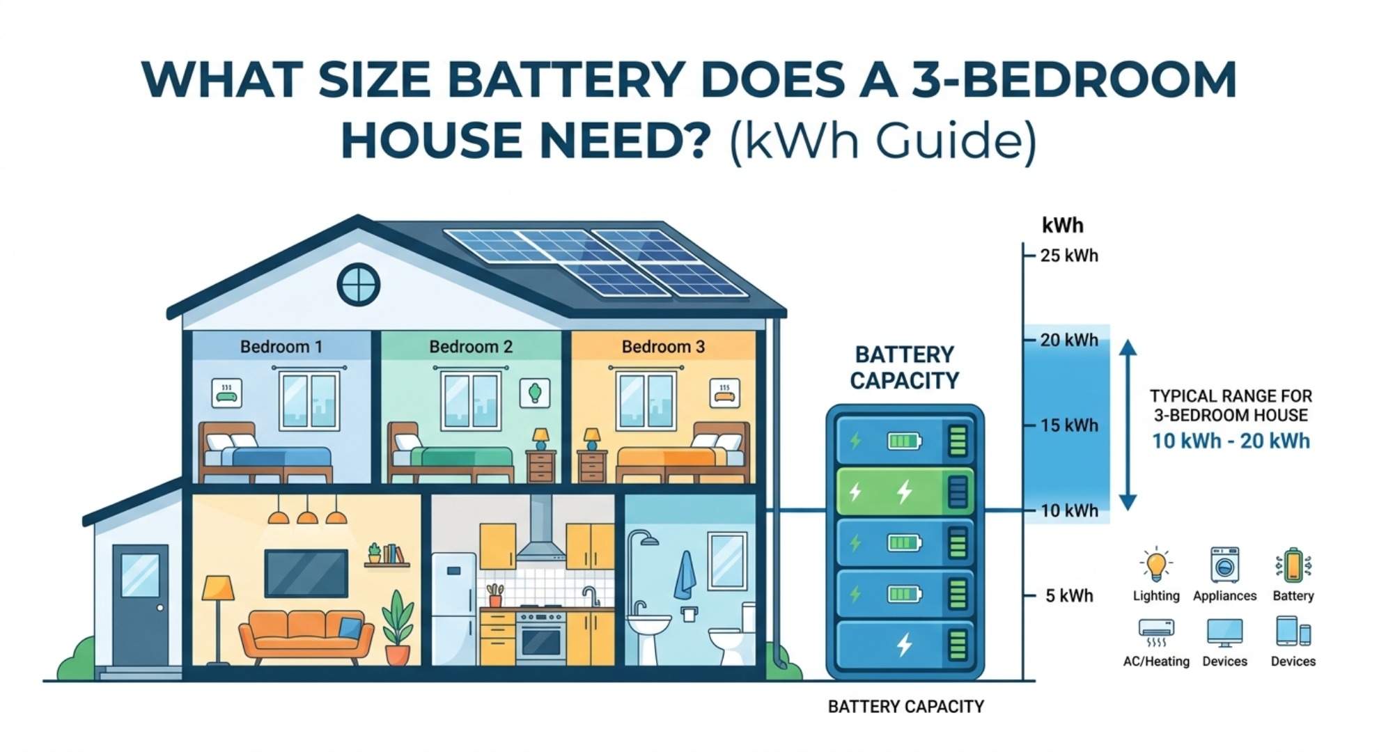
How to Calculate the Right kWh Capacity