


LFP Battery Degradation: How the SEI Layer Affects Lifespan
LFP Battery Degradation: How the SEI Layer Affects Lifespan

Table of Contents
LFP Battery Degradation and Capacity Fade Explained

Lithium iron phosphate chemistry is renowned across the energy storage industry for its exceptional safety profile, high thermal stability, and extended cycle life. However, even the most durable cells suffer from gradual electrochemical aging over time. During thousands of charge‑discharge cycles, users observe LFP battery capacity loss that slowly reduces total usable energy storage. While cathode dissolution and structural cracking plague other lithium‑ion chemistries, degradation in phosphate‑based cells follows a distinct, anode‑dominated path driven primarily by side reactions at the liquid‑solid interface.
Unlike nickel‑ or cobalt‑based chemistries that undergo crystal lattice collapse under high stress, phosphate cells benefit from a highly rigid olivine crystal structure. Because the cathode framework remains exceptionally stable, lithium iron phosphate degradation is predominantly caused by the progressive loss of active lithium ions at the negative graphite electrode. Understanding these microscopic interfacial reactions is essential for optimizing battery energy storage systems in both residential and commercial applications.
What Is the SEI Layer? Structure, Formation, and Growth

At the core of graphite electrode chemistry is the solid electrolyte interphase, commonly referred to as the SEI layer. This microscopic passivating film forms spontaneously on the surface of the synthetic or natural graphite anode during the very first electrochemical charge of a cell. Functionally, a healthy SEI acts as a selective electrochemical membrane: it allows positively charged lithium ions to pass through during intercalation while preventing bulk solvent molecules in the liquid electrolyte from directly contacting the conductive carbon surface.
During the factory battery formation process, controlled initial charges decompose liquid organic solvents and electrolyte salts, producing a complex protective coating. This film consists of an inner layer rich in inorganic compounds (such as lithium fluoride and lithium carbonate) and an outer porous organic layer. This initial passivating film is critical; without it, continuous electrolyte breakdown would rapidly consume active material and destroy cell equilibrium within a few operational cycles.
| SEI Layer Component | Primary Chemical Compounds | Functional Role in Cell Health |
|---|---|---|
| Inner Layer (Inorganic) | LiF, Li₂CO₃, Li₂O | Provides mechanical strength and selective ion transport |
| Outer Layer (Organic) | (CH₂OCO₂Li)₂, Lithium Alkyl Carbonates | Buffers volume expansion and absorbs liquid electrolyte |
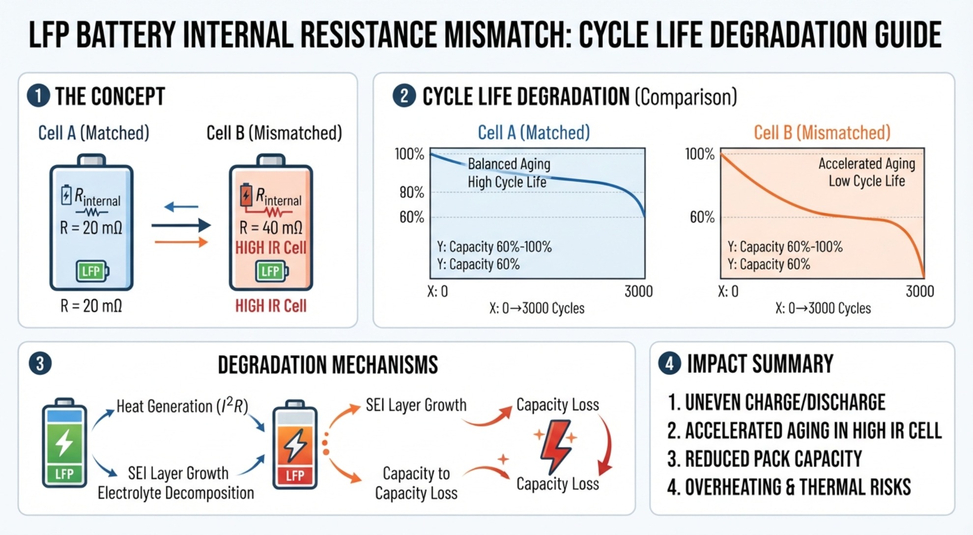
However, this protective barrier is not entirely static over years of operation. Periodic expansion and contraction of graphite particles during daily cycling cause micro‑cracking across the passivating boundary, exposing fresh carbon surfaces to liquid electrolyte. As solvent molecules react with newly exposed graphite, ongoing chemical decomposition consumes additional active ions, resulting in persistent active lithium inventory loss and gradual capacity loss over the lifespan of the battery.
Factors That Accelerate SEI Layer Growth in LFP Batteries

Environmental conditions play a direct role in governing the rate of chemical aging within a cell. Exposure to high temperature battery storage dramatically speeds up parasitic reactions at the anode interface. When internal thermal limits exceed optimal operating bounds, inorganic compounds within the protective film begin to dissolve or thermally decompose. This disruption triggers aggressive secondary film thickening, locking away mobile lithium ions into irreversible chemical compounds.
Charging profiles and electrical stress also exert strong physical influences on the anode interface. High C‑rate fast charging generates steep ion concentration gradients and localized mechanical stress across graphite particles. Under heavy current loads or low ambient temperatures, lithium ions cannot intercalate into the carbon matrix quickly enough, causing metallic lithium to deposit on the anode surface—a phenomenon that damages the passivating film and increases internal impedance.
| Operating Variable | Primary Degradation Mechanism | Impact on Battery Health |
|---|---|---|
| High Temperatures (> 45°C) | Thermal dissolution of inorganic SEI components | Rapid capacity fade and electrolyte dry‑out |
| High C‑Rate Charging | Mechanical cracking of film & lithium plating | Increased internal resistance & power fade |
| High Depth of Discharge (DoD) | Severe volumetric expansion/contraction | Accelerated film fracture and continuous regrowth |
Furthermore, operating continuously at extreme voltage limits accelerates interphase wear. Maintaining a high Depth of Discharge (DoD) cycling regime subjects the graphite lattice to maximal mechanical expansion and compression. This continuous physical movement fractures the passivating layer repeatedly, accelerating solvent decomposition and internal resistance buildup.
How to Minimize SEI Degradation and Extend Battery Life

Mitigating long‑term chemical degradation requires a combination of precise hardware engineering and intelligent software control. Modern Battery Management System (BMS) algorithms continuously monitor individual cell voltages, current densities, and temperature gradients. By dynamically adjusting charge currents based on real‑time cell state and thermal feedback, the BMS prevents operating conditions that favor aggressive layer thickening or metallic plating.
Effective thermal management infrastructure is equally crucial for long‑term storage health. Integrating active liquid cooling or advanced phase‑change materials ensures that LFP thermal management maintains uniform temperature distribution across every cell in a module. Maintaining operating temperatures within an ideal window of 15°C to 35°C minimizes both thermal dissolution at high temperatures and lithium plating risk at lower temperatures.
Finally, optimizing daily operational habits significantly extends calendar and cycle life. Applying a moderate operating SOC range—such as keeping daily storage cycles between 10% and 90% state of charge—reduces peak mechanical stress on the graphite structure. This operational approach slows passive interphase growth, minimizes internal resistance accumulation, and maximizes the overall return on investment for energy storage infrastructure.
Prismatic vs Cylindrical LFP Cells: Which Is Better for Home Storage?
LFP vs Sodium Ion Battery Technical Comparison