


Active vs Passive BMS Balancing: Which Is Better for Battery Packs?
Active vs Passive BMS Balancing: Which Is Better for Battery Packs?

Contents
- BMS Cell Balancing Fundamentals and Working Principles
- Passive Cell Balancing: How Bleed Resistors Work
- Active Cell Balancing: How Charge Redistribution Works
- Active vs Passive BMS Balancing: Key Differences
- Energy Efficiency and Thermal Management in BMS
- Balancing Current, Speed, and Cell Capacity Limits
- Circuit Complexity, Component Count, and Reliability
- Choosing the Right BMS Balancing Strategy for Your Pack
- When Passive BMS Balancing Is the Best Choice
- When Active BMS Balancing Is Essential for Performance
Keeping individual cells well‑matched inside multi‑cell lithium battery packs directly impacts usable capacity and helps avoid unexpected safety shutdowns. Your battery management system (BMS) handles this cell equalization with either passive or active balancing hardware. There is no universal “best” option. Your final call depends on real‑world operating cycles, battery chemistry, cell size, and thermal constraints of your hardware design.
BMS Cell Balancing Fundamentals and Working Principles
Passive Cell Balancing: How Bleed Resistors Work
Passive balancing works by burning away excess energy to bring series‑connected cells toward the same state of charge (SOC). As charging nears completion, the BMS tracks voltage drift cell‑by‑cell. Whenever a cell with higher effective capacity or lower internal resistance hits the balancing voltage threshold, an on‑board MOSFET switches in a bleed resistor across that cell. Extra energy dissipates as heat. This continues until remaining cells catch up to the target voltage level.
Active Cell Balancing: How Charge Redistribution Works
Active balancing uses power electronics to move charge from higher‑energy cells over to weaker ones instead of throwing power away as heat. Three common circuit approaches show up in modern active balancers: switched‑capacitor designs, inductive buck‑boost converters, and isolated flyback transformers. Energy transfers can run during charge, discharge, or when the battery sits idle. Real‑world transfer efficiency lands between 80 % and 95 %, cutting total system energy loss significantly.
Active vs Passive BMS Balancing: Key Differences
| Technical Parameter | Passive BMS Balancing | Active BMS Balancing |
|---|---|---|
| Operating Mechanism | Energy Dissipation (Resistor Heat) | Energy Redistribution (Inductive/Capacitive Transfer) |
| Balancing Current Range | 50 mA – 250 mA | 0.5 A – 6.0 A |
| Energy Efficiency | Low (~0% for dissipated current) | High (80% – 95% transfer efficiency) |
| Active States | Top‑of‑charge absorption only | Charge, discharge, and standby/idle |
| Thermal Footprint | Concentrated localized heat generation | Minimal thermal output |
| Circuit Complexity | Simple (Low component count) | Complex (High MOSFET/inductor count) |
| Relative Hardware Cost | Baseline (Economical) | 3x – 5x higher BOM cost |
Energy Efficiency and Thermal Management in BMS

These two balancing methods create very different thermal conditions inside battery enclosures. Passive hardware turns excess power into heat through resistors. Run higher balancing currents and you get strong local heat buildup within sealed battery housings. You must plan thermal handling carefully, otherwise nearby cells will degrade faster over time. Active balancing generates far less waste heat. That makes it a practical fit for densely packed battery assemblies or passive‑cooled systems with limited heat‑removal capability.
Balancing Current, Speed, and Cell Capacity Limits

Balancing speed comes down to the maximum safe current your circuit supports. Thermal limits cap passive balancing; most implementations stay below 250 mA. Take large prismatic cells like the 200 Ah‑304 Ah units common in battery energy storage (BESS). A typical 100 mA passive balancer may need multiple days of float charging just to fix large voltage gaps between cells. Active balancers deliver continuous current from 1 A up to 6 A. They can equalize those same large‑capacity battery strings within hours.
Circuit Complexity, Component Count, and Reliability
Design engineers assessing real‑world field performance must weigh circuit complexity against potential failure points. Passive balancing pairs an analog front‑end (AFE) with basic MOSFETs and resistors. These setups deliver very low FIT (failure‑in‑time) rates, and deep‑sleep standby current sits under 10 µA. Active designs add many switching ICs, power inductors and transformers. More parts create more points of failure. They are also more prone to EMI noise issues. Without proper sleep‑mode firmware, standby parasitic power draw also rises.
Choosing the Right BMS Balancing Strategy for Your Pack
When Passive BMS Balancing Is the Best Choice
Passive balancing still makes up over 90 % of deployed commercial battery hardware. You will see it widely used for residential solar storage and light electric vehicles. It is the practical pick under these conditions:
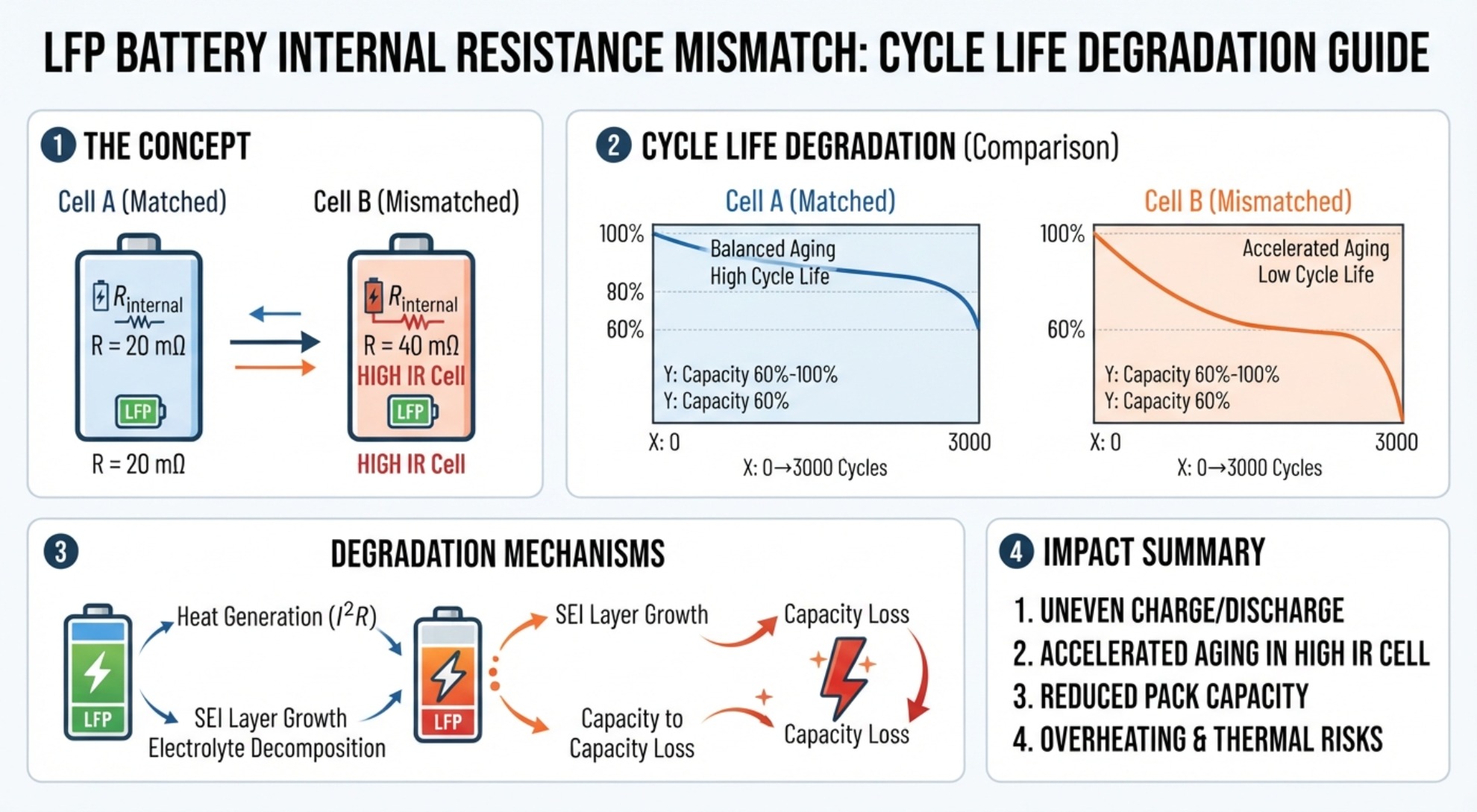
- High‑Grade Cells Are Used: If your pack uses well‑matched factory‑sorted LiFePO4 or NMC cells, capacity mismatch often stays below 1 %. Low‑current passive balancing holds cell balance reliably in this scenario.
- Budget and Space Are Constrained: Projects working with limited PCB real‑estate and tight BOM cost targets benefit most from passive balancing hardware.
- Long Standby Requirements Exist: Batteries that sit in storage for long stretches without grid charging need the ultra‑low micro‑amp sleep currents typical of passive AFE chips.
When Active BMS Balancing Is Essential for Performance
Active balancing brings clear performance gains when hardware operates under tough conditions or uses cells with inherent mismatch:
- Large‑Capacity Prismatic Configurations: Passive balancing moves too slowly for battery strings built around 300 Ah+ cells. Higher active balancing currents stop cell‑to‑cell drift through repeated charge‑discharge cycles.
- Second‑Life Battery Modules: Repurposed lithium cells frequently show wide spread in internal resistance and usable capacity. Active charge redistribution helps you extract more total runtime out of these packs.
- High Duty‑Cycle Operations: Heavy‑duty commercial EVs and fast‑response grid‑regulation systems cycle rapidly with little float‑charge downtime. These systems need balancing working both during charge and discharge phases to avoid unexpected voltage‑based cut‑offs.
Your final choice between active and passive balancing needs to factor in cell quality, total pack capacity, real operating duty cycles, and hardware budget. Passive balancing gives solid reliability and straightforward operation for cost‑sensitive builds using well‑matched cells. Where you run large‑capacity strings, dynamic cycling profiles, or packs with significant cell divergence, active balancing’s high‑current charge transfer unlocks more usable energy from your battery pack.
Grade A vs Grade B LFP Cells: How to Spot Quality Differences