


LFP Battery Sizing vs Later Parallel Expansion
LFP Battery Sizing vs Later Parallel Expansion – Technical Field Guide

Table of Contents
Lithium‑iron‑phosphate (LFP) batteries are widely used for solar‑based energy storage. System designers often face a practical choice: build out full battery capacity during initial commissioning, or start smaller and add parallel battery packs later. Each option brings real trade‑offs in cost, reliability and service life. Designing a reliable solar energy storage system requires balancing immediate power requirements with future energy demands. Selecting the correct LFP battery sizing from day one prevents operational bottlenecks, whereas opting for parallel battery expansion later provides financial flexibility at the expense of technical complexity. Achieving long‑term system efficiency requires evaluating how capacity planning, electrochemical degradation, and battery management protocols interact over time.
Initial Battery Bank Sizing and Staged Capacity Expansion

Calculating the initial usable capacity of a lithium iron phosphate battery involves evaluating the facility's daily kilowatt‑hour load alongside autonomy requirements. In an off‑grid solar design, sizing the battery bank to cover 100% of current and anticipated loads eliminates the risks associated with retrofitting aging infrastructure. Installing the entire capacity upfront ensures uniform cell chemistry, identical state of health (SoH), and balanced internal impedance across all parallel branches.
Staging a battery energy storage system through incremental modular additions reduces the upfront capital expenditure, lowering the entry barrier for residential and commercial installations. This approach optimizes the levelized cost of storage by deferring capital investment until energy consumption increases. However, retrofitting additional modules into an existing DC bus requires careful planning to prevent system imbalance and premature capacity fade.
Full‑capacity deployment simplifies commissioning and avoids later‑time compatibility issues. Staged expansion lets users hold off large spending when future load growth is unclear. No single solution fits every site; decisions should be based on budget, load forecasts, and long‑term operating plans.
+-------------------------------------------------------------------------------+
|                        PARALLEL BATTERY SYSTEM ARCHITECTURE                   |
+-------------------------------------------------------------------------------+
|                                                                               |
|  +--------------------+    +--------------------+    +--------------------+  |
|  | Battery Module A   |    | Battery Module B   |    | Expansion Pack C   |  |
|  | (Aged Pack)        |    | (Aged Pack)        |    | (New Pack)         |  |
|  | Higher R_int       |    | Higher R_int       |    | Lower R_int        |  |
|  +---------+----------+    +---------+----------+    +---------+----------+  |
|            |                         |                         |              |
|            +------------+------------+------------+------------+              |
|                         |                         |                           |
|                  [ Master BMS ]            [ Parallel DC Bus ]                |
|                         |                         |                           |
+-------------------------|-------------------------+---------------------------+
                          v                         v
                     [ Inverter ] <=======> [ Electrical Load ]
Load Assessment, Upfront Capital and Expansion‑Related Costs
Base‑Load and Peak‑Energy Consumption Evaluation
Determining the system's continuous load rating and peak surge capacity forms the baseline for inverter matching and battery power output. Inductive loads—such as compressors, well pumps, and HVAC systems—require high instantaneous discharge currents without causing voltage sag. Under‑sizing the initial battery capacity forces the system to operate at elevated C‑rates, accelerating heat generation and shortening overall service life.
Many site errors come from only looking at average daily consumption and ignoring short‑term peak surges. Inductive equipment can push transient current well above nominal operating values and stress undersized battery hardware.
CAPEX Comparison: Full‑Sized Installation vs Phased Expansion
An initial battery installation designed with headroom minimizes total installation labor, commissioning fees, and balance of system costs. While buying extra capacity today increases initial hardware expenditures, configuring a modular battery rack for later expansion introduces hidden expenses, including additional DC disconnects, heavier busbars, and compatible multi‑pack control hardware.
These balance‑of‑system costs are often overlooked in early budgeting. Project owners frequently expect expansion work to only require new battery modules. Wiring, protection gear and BMS compatibility add significant cost during later retrofit work.
| Evaluation Metric | Full Initial Sizing (1‑Step) | Later Parallel Expansion (Modular) |
|---|---|---|
| Upfront CAPEX | Higher initial investment | Lower entry cost |
| Cell Degradation Match | Perfectly uniform across all cells | Mismatched cell age and internal resistance |
| System Balance | Self‑equalizing parallel branches | Requires active BMS parallel management |
| BOS & Wiring Complexity | Standardized cable lengths and fuses | Oversized DC busbars and additional switches |
| Usable Capacity Utilization | 100% rated capacity available | 80%–90% effective utilization due to voltage trim |
Technical Risks of Retrofitting Parallel LFP Battery Packs
Connecting a new pack to an aged parallel LFP battery connection exposes the system to cell aging degradation and severe internal resistance mismatch. As lithium iron phosphate batteries undergo charge‑discharge cycling, their internal resistance increases while nominal capacity decays. When a low‑resistance new module is wired alongside an high‑resistance older pack, current distribution becomes non‑uniform, leading to cross‑pack circulating currents.
Field note: do not apply lead‑acid parallel‑wiring experience directly to LFP. LFP’s flat voltage plateau amplifies imbalance effects that would be acceptable for lead‑acid batteries.
| Aging Factor | Legacy Battery Pack | Newly Added Battery Pack | Technical Consequence |
|---|---|---|---|
| Internal Resistance (R_int) | High | Low | New pack absorbs higher charge/discharge current |
| State of Health (SoH) | Degraded (<85%) | Prime (100%) | Old pack reaches voltage cutoffs prematurely |
| Voltage Response Under Load | Steeper voltage drop | Stable flat voltage | Current imbalance during high discharge loads |

The extremely flat voltage curve of LFP chemistries exacerbates these challenges. A minute voltage differential between parallel strings represents a substantial state of charge alignment gap. Consequently, the newly added module may supply up to 70% of the total load current during heavy discharge events, resulting in undercharging new cells and preventing the system from ever utilizing the full rated capacity of the combined battery bank.
       Discharge Current Distribution (Parallel Strings)

Total Load Current (100A)
  │
  ├──────► Legacy Pack (High R_int)  ──► [ 30A Current Share ]
  │
  └──────► New Pack (Low R_int)     ──► [ 70A Current Share ] (Overloaded)
Pack‑to‑Pack Voltage Mismatch and Circulating Current
When two parallel strings with unequal open circuit voltage values are joined, current flows directly from the higher‑voltage pack into the lower‑voltage pack without passing through the load inverter. Because LFP displays a near‑flat discharge plateau between 20% and 80% SoC, even a 0.2V variance can trigger significant busbar voltage equalization currents. Without pre‑charge circuits or active isolation, these high current surges can trip circuit breakers or damage BMS MOSFETs.
Internal Resistance Variation and Capacity Mismatch
Variations in battery internal impedance alter the dynamic C‑rate distribution across parallel strings. During high‑power charge cycles, the new battery pack with lower resistance absorbs current faster than the older pack. The old pack hits its upper voltage threshold early, forcing the charge controller to enter absorption mode before the new pack completes its charge, causing premature thermal degradation and cycle life reduction.
Over years of operation this imbalance creates a feedback loop. Older packs degrade faster because they never reach full charge. Newer packs carry excess current and wear out ahead of expected service life.
BMS Design Requirements for Multi‑Pack Parallel Systems

Integrating a advanced battery management system with active parallel management is critical when expanding energy storage capacity over time. A centralized or daisy‑chained system uses CAN bus communication to monitor individual pack voltages, temperatures, and state‑of‑charge values. Installing properly rated DC bus bar sizing ensures minimal voltage drop between parallel strings and prevents localized overheating.
One common site mistake: paralleling multiple independent standalone‑BMS battery packs. Most consumer‑grade standalone BMS units have no cross‑pack coordination. They cannot suppress circulating currents, creating safety and performance risks for retrofit expansion. Only controllers built for multi‑pack parallel operation should be used for staged‑growth systems.
          Active Parallel Isolation Circuit Architecture

  +-------------------+        +-------------------+
  | Legacy Pack (A)   |        | New Pack (B)      |
  | SoH: 80%          |        | SoH: 100%         |
  +---------+---------+        +---------+---------+
            |                            |
      [ DC Breaker ]               [ DC Breaker ]
            |                            |
     [ Bidirectional ]            [ Bidirectional ]
     [ DC‑DC Limiter ]            [ DC‑DC Limiter ]
            |                            |
            +-------------+--------------+
                          |
                   [ Main DC Bus ]
                          |
                    [ Inverter ]
Advanced multi‑pack controllers feature bidirectional DC‑DC current limiters or intelligent isolation switches to safely manage incoming expansion modules. These systems conduct continuous state of health monitoring and automatically balance current flow across asymmetrical strings. Integrating dedicated overcurrent protection, appropriately rated DC circuit breakers, and an isolated modular expansion cabinet safeguards the electrical installation against short‑circuit hazards and reverse polarity events.
Field Engineering Best Practices for LFP Battery Bank Scaling
To maximize lifespan and efficiency when expanding lithium iron phosphate systems, follow these field‑tested installation guidelines:
- Implement Matched Cable Lengths: Utilize identical cable gauges, lengths, and terminal lugs across all parallel connections to equalize circuit resistance.
- Voltage Match Before Interconnection: Charge or discharge the expansion module until its open‑circuit voltage is within 0.1V of the existing battery bank before closing the parallel breaker.
- Manage Temperature Coefficients: Maintain uniform ambient temperatures across all packs in the enclosure to prevent thermal‑induced resistance variations.
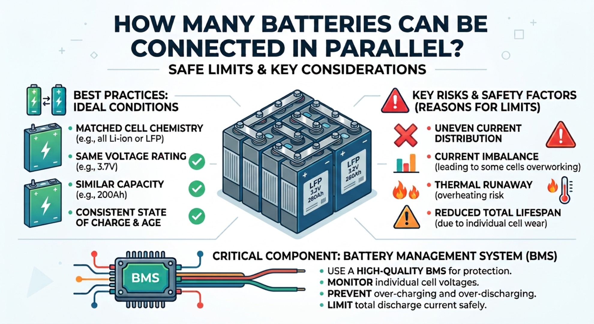
- Adhere to Parallel Module Limits: Restrict the maximum number of parallel strings according to the manufacturer's BMS communication protocol constraints.
- Perform Periodic Calibration: Conduct full charge‑discharge recalibration cycles annually to re‑align state‑of‑charge algorithms and clear capacity drift errors.
LFP Expansion Risks: The Voltage Gap Problem
15kWh LFP Industrial Battery Storage Case Study