


How Many Batteries Can Be Connected in Parallel?
How Many Batteries Can Be Connected in Parallel? Safe Limits
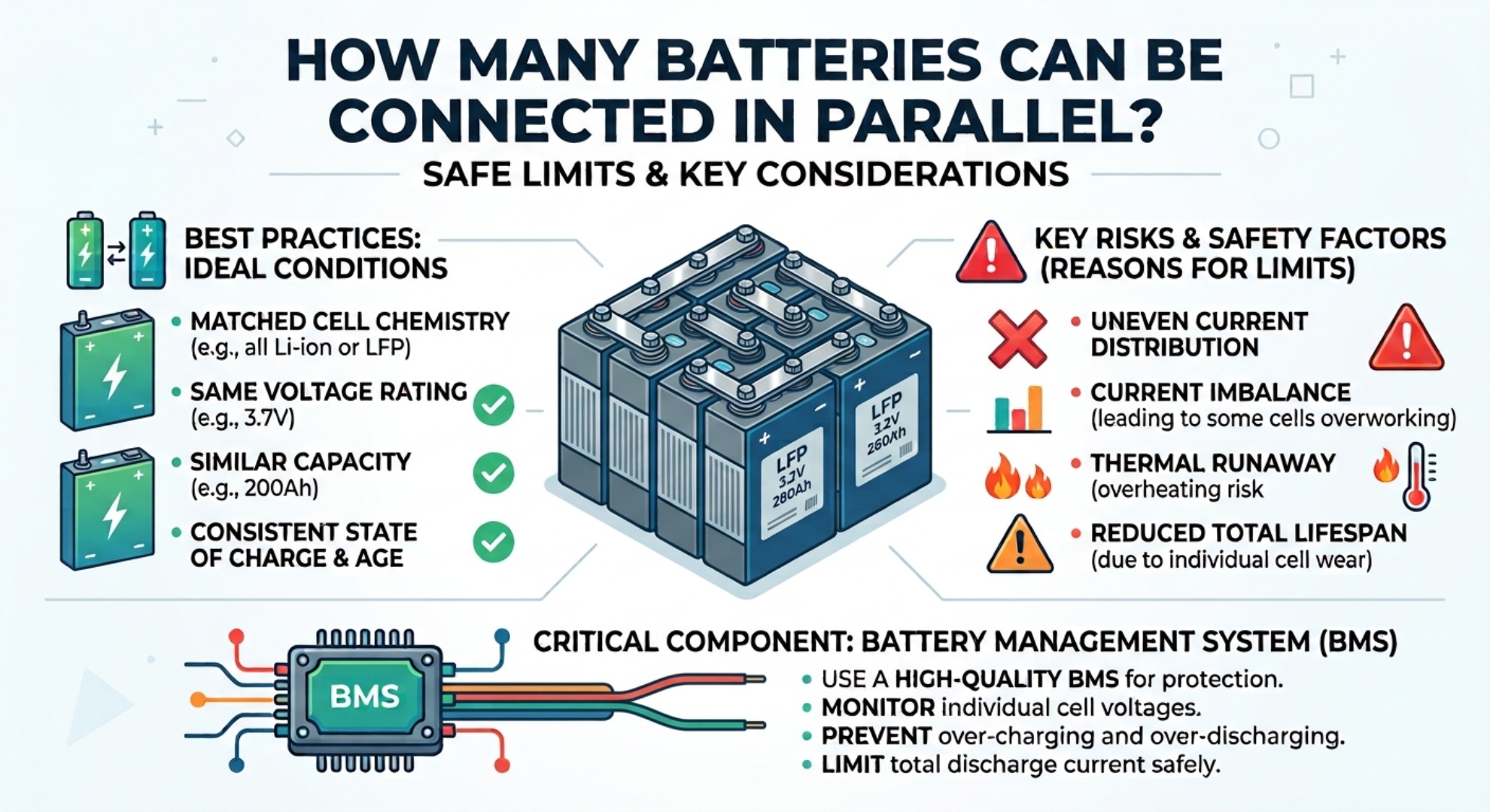
Table of Contents
- Parallel Battery Wiring: Voltage and Capacity Explained
- How Parallel Connections Increase Battery Amp‑Hours
- How Many Batteries Can You Wire in Parallel? Real Limits
- Max Parallel Batteries: Lead‑Acid vs LiFePO4 Limits
- Key Factors Limiting Parallel Battery Connections
- BMS Synchronization and Busbar Design
- Voltage Imbalance and Circulating Current Risks
- Safe Step‑by‑Step Parallel Battery Setup
- Best Practices to Prevent Overheating and Aging
- Real‑World Installation Case Study
- Frequently Asked Questions (FAQ)
When expanding an off‑grid solar setup or backup power system, determining how many batteries can be connected in parallel is a fundamental engineering question. In theory, you can connect an infinite number of identical cells in parallel because parallel connections maintain a constant system voltage while multiplying overall amp‑hour capacity. In practical applications, physical factors—including internal resistance differentials, cable resistance, and management system limitations—impose strict practical limits.
Parallel Battery Wiring: Voltage and Capacity Explained
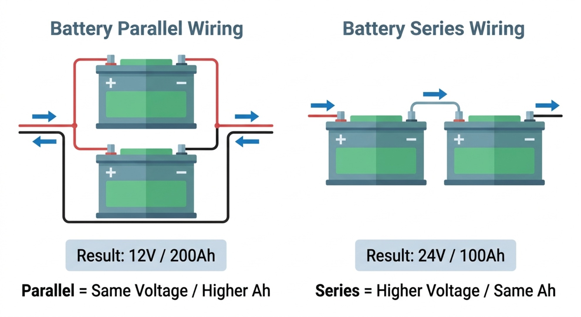
Connecting multiple energy storage modules in parallel requires joining all positive terminals to a common positive rail and all negative terminals to a common negative rail. Unlike a series configuration—which stacks individual module voltages to achieve higher system voltage—a parallel battery connection keeps nominal voltage identical to a single unit while summing the cumulative current. For instance, wiring four 12V 100Ah modules in parallel creates a combined 12V 400Ah power bank capable of sustaining loads for four times longer.
How Parallel Connections Increase Battery Amp‑Hours
The primary objective of a parallel configuration is extending system runtime without requiring higher‑voltage inverters or charge controllers. By increasing available battery amp‑hour ratings, the total stored energy expands proportionally without altering DC distribution hardware. However, as additional units join the bank, current distribution across each parallel branch becomes highly sensitive to minute differences in conductor resistance, terminal torque, and internal cell degradation. Understanding usable capacity also ties closely to Depth of Discharge (DOD) for lithium‑based energy storage systems.
How Many Batteries Can You Wire in Parallel? Real Limits
| Battery System Aspect | Theoretical Parallel Configuration | Practical Real‑World Configuration |
|---|---|---|
| System Voltage | Unchanged regardless of unit count | Constant nominal voltage maintained |
| Total Amp‑Hour Capacity | Infinite sum of individual Ah ratings | Typically limited to 4–16 modules in parallel |
| Current Distribution | Perfectly equal across all branches | Dictated by branch cable length and internal resistance |
| Safety Risks | Zero resistance assumed | Thermal imbalance, circulating currents, short circuits |
While mathematical models suggest endless scalability, real‑world electrical laws impose a strict maximum parallel battery limit. When batteries are wired together, the unit with the lowest internal resistance naturally supplies or absorbs a disproportionate share of current. If too many modules are connected in a single row, current imbalance creates localized heat generation, accelerated aging, and potential cascading thermal issues across the system.
Max Parallel Batteries: Lead‑Acid vs LiFePO4 Limits
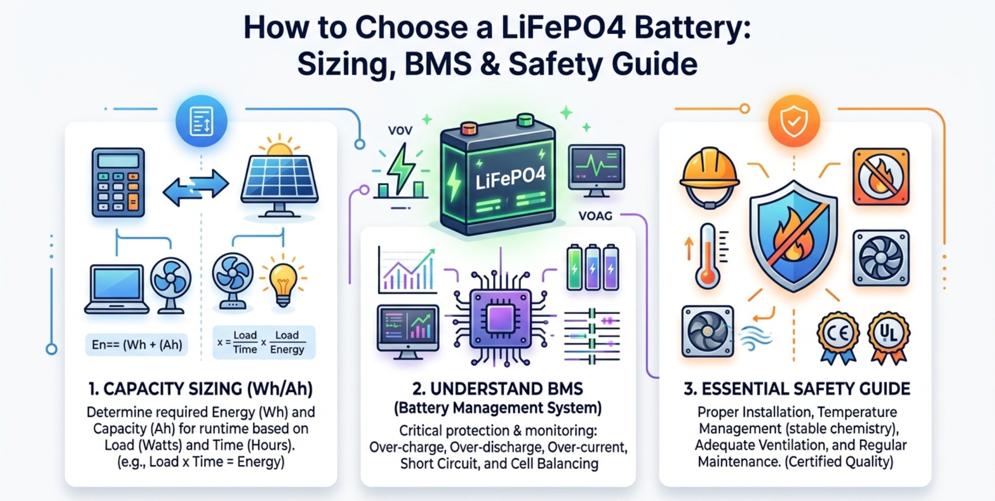
For traditional flooded lead‑acid, AGM, or GEL power packs, industry standards strongly recommend connecting no more than 4 batteries in parallel. Lead‑acid cells suffer from high internal resistance variations and self‑discharge rates, causing cross‑charging currents that prematurely destroy unmonitored branches. Conversely, modern Lithium Iron Phosphate (LiFePO4) systems feature integrated electronic protection, allowing up to 16 units in parallel when properly synchronized via digital communication protocols. Before purchasing battery hardware, review our complete LiFePO4 buying and sizing guide for key selection criteria.
Key Factors Limiting Parallel Battery Connections
BMS Synchronization and Busbar Design
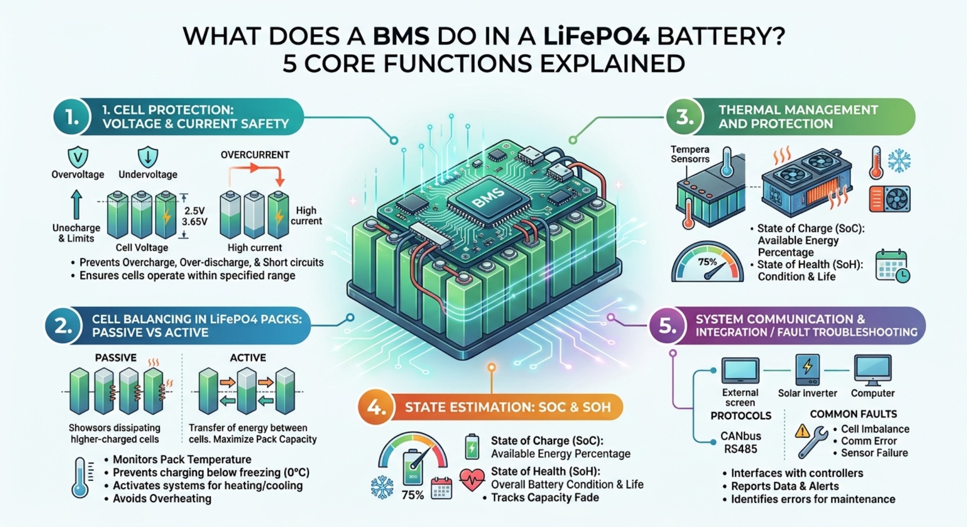
In advanced lithium installations, the primary bottleneck is not chemical capability but BMS communication protocols. Each smart battery relies on a Battery Management System (BMS) to monitor cell voltages, state of charge (SOC), and temperature limits. When expanding a bank, the master controller must process real‑time telemetry from every slave unit to ensure contactors close safely; exceeding manufacturer‑specified parallel limits disables closed‑loop inverter communication and leads to system shutdown.
Voltage Imbalance and Circulating Current Risks

A major hazard in poorly designed setups is circulating current between batteries. If a fully charged module at 13.6V is connected in parallel with a discharged module at 12.0V, electricity flows rapidly from the higher‑potential unit into the lower‑potential unit without load resistance. This uncontrolled transfer creates extreme amperage spikes, potentially tripping internal breakers, melting terminal posts, or triggering thermal runaway.
Safe Step‑by‑Step Parallel Battery Setup
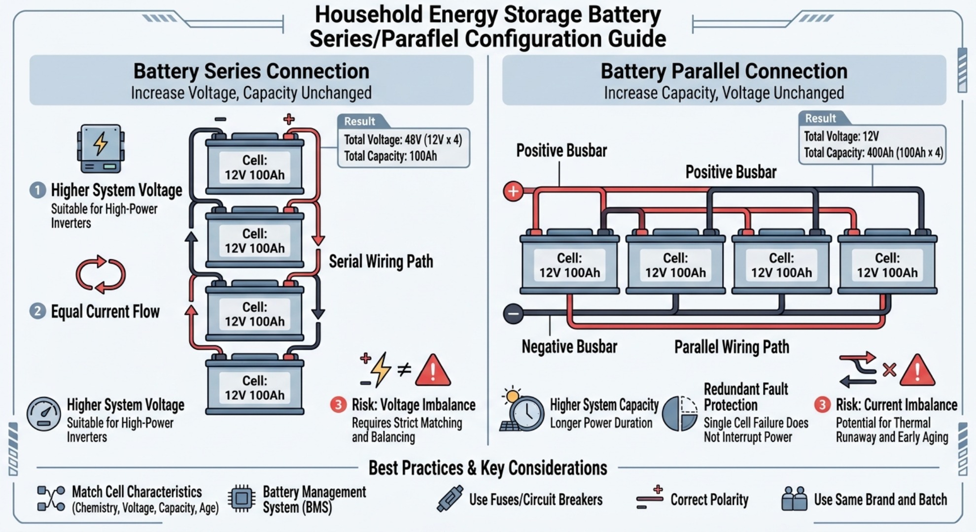
To ensure long‑term stability and optimal current balance, follow these essential engineering rules during installation:
- Match Chemistry, Age, and Capacity: Never combine different battery chemistries (e.g., lithium with AGM), mixed capacities, or old cells with new cells.
- Standardize Cable Lengths and Gauges: Ensure every branch cable connecting a battery to the collector point has identical gauge, length, and crimped lug resistance to guarantee equal current draw.
- Utilize Heavy‑Duty Busbars: Avoid daisy‑chaining terminals in a line; instead, connect each module directly to a central positive and negative busbar using cross‑diagonal wiring principles.
- Install Branch‑Level Fusing: Mount an appropriately rated overcurrent protection fuse or circuit breaker on the positive terminal of every parallel branch before it meets the main rail.
- Equalize Open‑Circuit Voltage Prior to Connection: Measure every unit with a digital multimeter to confirm voltage differences stay within 0.1V before joining terminals.
Best Practices to Prevent Overheating and Aging
Proper maintenance and initial commissioning determine the operational lifespan of a multi‑battery array. Prior to final parallel wiring, charge each module individually to 100% State of Charge (SOC) so cell balancing routines can equalize resting voltages. Routine thermal inspection using infrared thermometers ensures that no single terminal joint is experiencing excessive resistance, preserving system health across hundreds of charge cycles.
Real‑World Installation Case Study
Case 1: Off‑Grid Cabin AGM Battery Failure (Bad Parallel Practice)
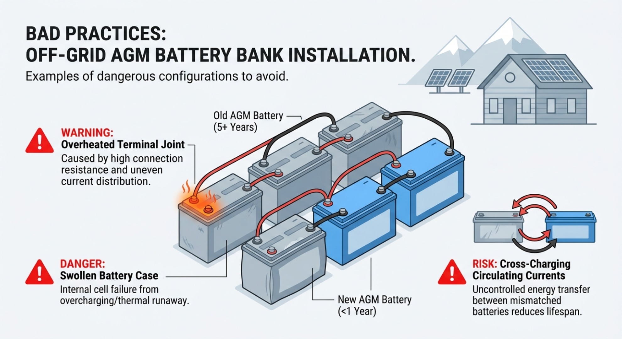
A remote off‑grid cabin owner installed six 12V 100Ah AGM lead‑acid batteries in parallel, exceeding the 4‑battery industry recommendation. He daisy‑chained batteries without branch fuses and mixed two new batteries with four 3‑year‑old used units. Within 8 months, circulating cross‑charging currents caused two older batteries to swell and fail. One terminal connection reached high temperature, triggering a near‑miss fire hazard. Replacing with four matched new AGM batteries with central busbars and branch fuses restored stable system operation for over 3 years.
Case 2: Successful LiFePO4 Parallel Solar Backup System
A residential solar backup system deployed eight identical smart 48V LiFePO4 batteries in parallel, following manufacturer maximum parallel specifications. All units used communication cables for BMS synchronization, equal‑length branch wiring, individual branch breakers, and pre‑equalized open‑circuit voltage. The bank delivers 800Ah total capacity for home backup during grid outages. After more than 1200 charge‑discharge cycles, thermal inspection shows balanced temperatures and minimal capacity drift across all battery modules.
Frequently Asked Questions (FAQ)
What Is DOD in a LiFePO4 Battery?