


What Does a BMS Do in a LiFePO4 Battery?
What Does a BMS Do in a LiFePO4 Battery? 5 Core Functions Explained
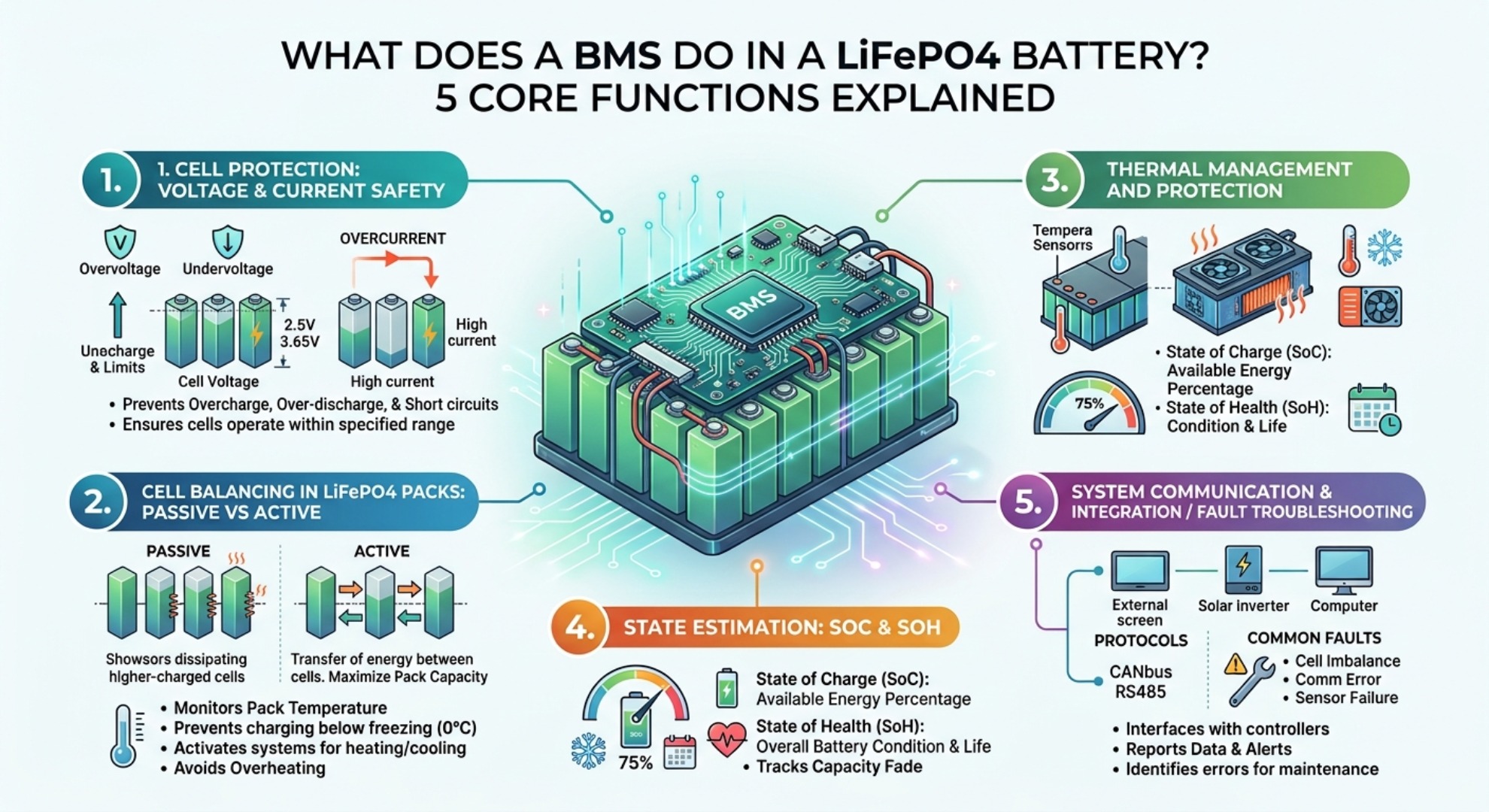
- How a BMS Protects LiFePO4 Cells: Voltage & Current Safety
- Cell Balancing in LiFePO4 Packs: Passive vs Active
- Thermal Management and Sub‑Zero Charging Protection
- SOC & SOH Estimation: How BMS Tracks Battery Health
- BMS Communication Protocols: CANbus, RS485, Inverter Integration
- Common BMS Faults and Troubleshooting
- Frequently Asked Questions
- Closing Notes
A Battery Management System (BMS) serves as the dedicated electronic brain of a lithium iron phosphate (LiFePO4) battery. While lithium iron phosphate chemistry offers exceptional inherent thermal stability and long cycle life, individual cells require continuous oversight to operate within precise electrical and thermal boundaries. The BMS constantly monitors parameters like individual cell voltage, total pack current, ambient temperature, and state of charge to ensure maximum safety, reliability, and operating efficiency.
LiFePO4 battery packs show up in many real‑world deployments. Common setups include 12.8‑volt RV and marine battery banks, 51.2‑volt residential off‑grid solar storage, and large‑scale commercial battery energy storage systems. Every installation relies on BMS hardware to keep series‑connected cells working within their design limits.
How a BMS Protects LiFePO4 Cells: Voltage & Current Safety
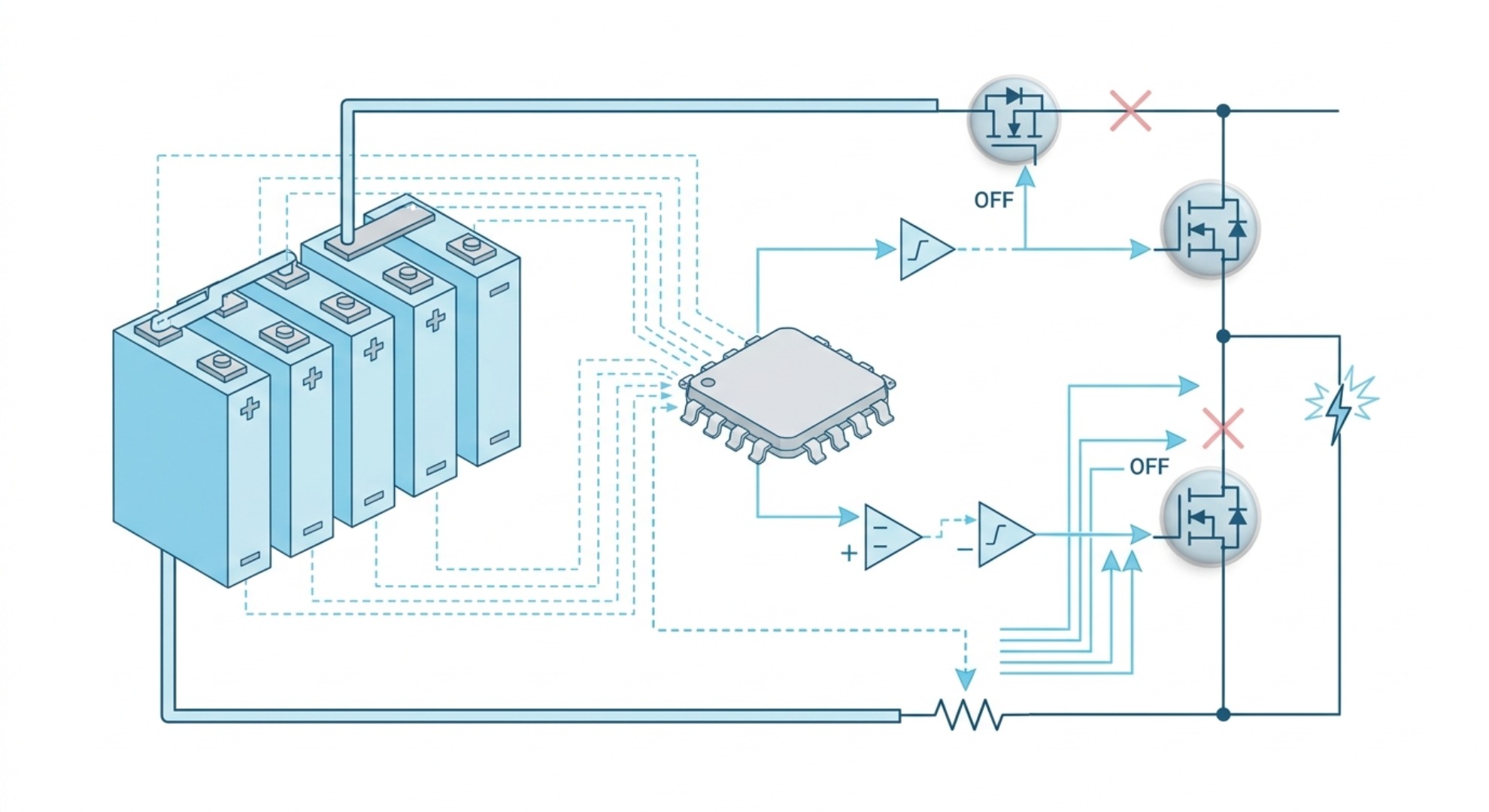
Safety is the primary objective of any battery protection system. Because lithium chemistry cannot tolerate electrical conditions outside its safe operating envelope, a BMS utilizes real‑time monitoring circuits and high‑speed electronic switches (MOSFETs or solid‑state contactors) to isolate the battery pack before physical damage or hazardous conditions develop.
Overcharge and Deep Discharge Protection
Individual LiFePO4 cells operate safely between an upper threshold of 3.65V and a lower limit of 2.50V. Exceeding 3.65V during charging forces excess lithium ions into the anode structure, causing electrolyte degradation, localized overheating, and capacity decay. The BMS continuously tracks per‑cell voltage, immediately opening the charge circuit when any cell reaches its limit. Conversely, over‑discharge protection cuts power output if any cell drops below 2.50V, preventing copper dissolution that leads to permanent capacity loss and internal short circuits.
Many BMS units store protection trigger events in internal memory. Some models latch off after critical faults. Manual disconnect and power cycle is often needed to clear latched protection states, depending on hardware design.
Overcurrent and Short‑Circuit Protection
Unexpected electrical surges or direct terminal short circuits can draw hundreds of amperes within milliseconds, creating rapid thermal buildups. The BMS integrates precision current shunts or Hall‑effect current sensors to measure load current flow continuously. When an abnormal current spike or short circuit is detected, the overcurrent protection circuit disconnects the load within microseconds, neutralizing explosion risks and protecting connected power electronics.
Cell Balancing in LiFePO4 Packs: Passive vs Active
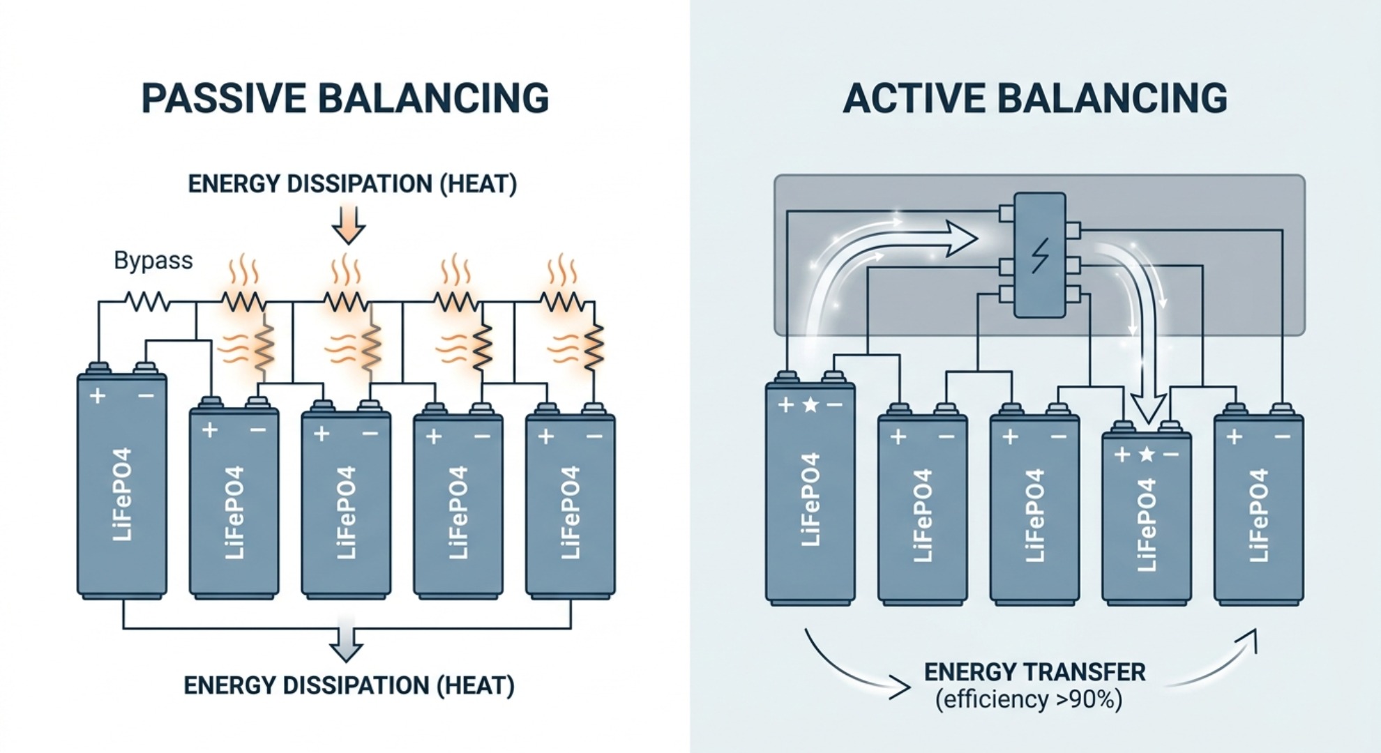
Multi‑cell energy storage packs are configured by connecting individual cells in series to achieve required system voltages—such as 4 cells for 12.8V, 16 cells for 51.2V, or higher counts for industrial arrays. Due to minor manufacturing variations in internal resistance and capacity, individual cell voltages diverge over repeated charge and discharge cycles. Without intervention, the weakest cell limits the usable capacity of the entire pack.
| Passive Balancing | Active Balancing |
|---|---|
| Dissipates excess charge as heat via resistors | Transfers energy from high cells to lower cells |
| Low cost, simple circuit Low current (50‑200mA) |
Higher efficiency, minimal heat generation (1A‑5A+) |
Passive vs Active Balancing Mechanisms Compared
The BMS resolves voltage imbalances using either cell voltage balancing method:
- Passive Balancing: During the final constant‑voltage (CV) charge phase, the BMS activates tiny bypass resistors across cells with higher voltages. Excess energy from fully charged cells bleeds off as heat, allowing slower‑charging cells to catch up until all cells align within a tight voltage spread (typically under 20mV).
- Active Balancing: Rather than wasting energy as heat, active balancing uses capacitive or inductive charge‑transfer circuits to shuttle energy directly from higher‑voltage cells into lower‑voltage cells. This process operates continuously during charge, discharge, and rest states, making it ideal for high‑capacity energy storage systems.
Passive balancing works fine for small home battery banks. Active balancing adds hardware cost, but it can recover 3‑8 percent of total usable pack capacity on large, long‑running storage installations.
Thermal Management and Sub‑Zero Charging Protection
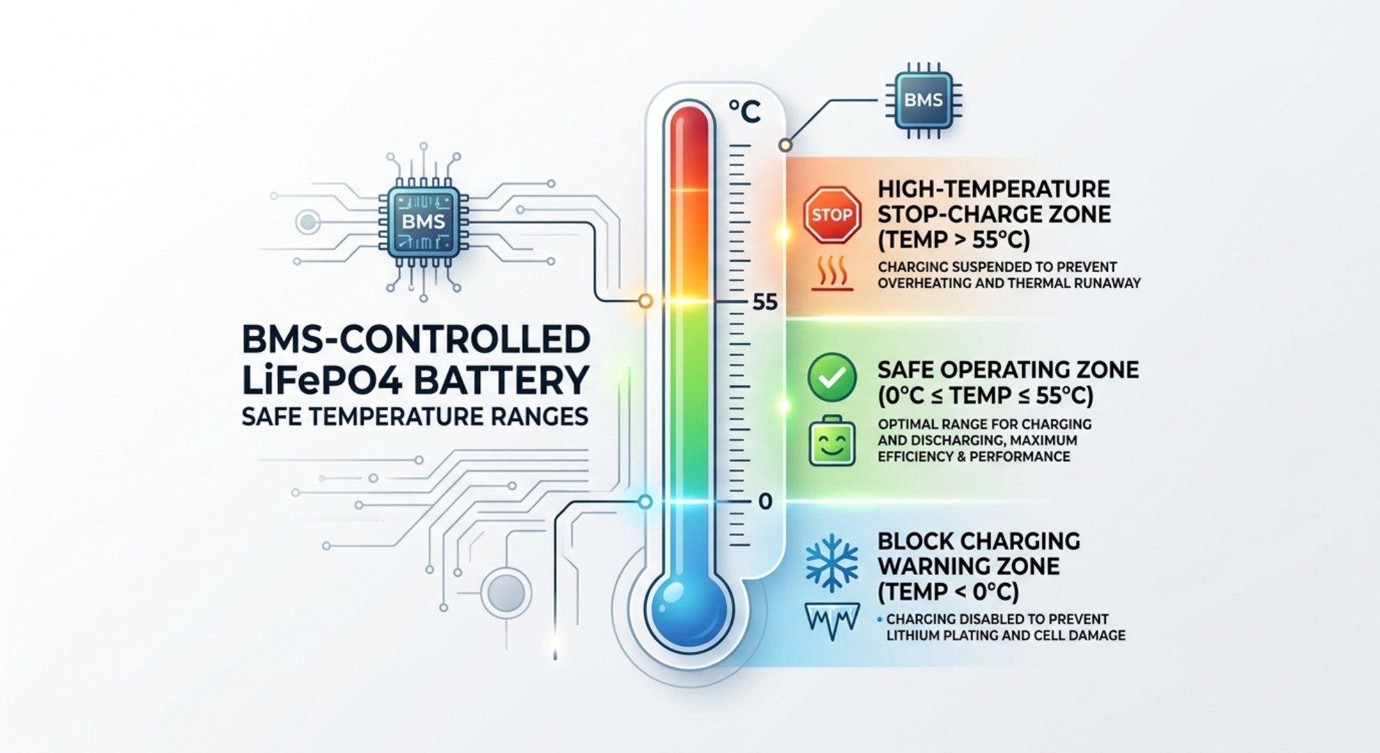
Temperature heavily dictates the chemical reactions inside a lithium iron phosphate battery. Thermal sensors connected directly to cell busbars feed real‑time temperature data to the BMS micro‑controller to prevent thermal damage.
When operating in elevated ambient temperatures (above 55°C / 131°F), the BMS halts charging to suppress thermal runaway pathways. Equally critical is low-temperature charging protection. Attempting to charge LiFePO4 cells at or below freezing (0°C / 32°F) causes metallic lithium to deposit directly onto the graphite anode rather than intercalating into it. This process, called lithium plating, creates micro-dendrites that can rupture the separator and cause internal short circuits. A modern BMS automatically blocks charge current below freezing while permitting normal discharge output. For a complete explanation of CC/CV stages, charging voltages and temperature limits, see our guide to how to charge a LiFePO4 battery safely .
Some industrial BMS hardware can trigger external heating elements or cooling fans tied to its control outputs. This closed‑loop hardware extends operating conditions for off‑grid sites exposed to extreme climate swings.
SOC & SOH Estimation: How BMS Tracks Battery Health
Unlike lead‑acid or nickel‑based chemistries, LiFePO4 features an extremely flat voltage discharge curve. A cell maintains approximately 3.20V to 3.25V across 20% to 80% of its discharge cycle, rendering simple voltage readings ineffective for predicting remaining battery capacity.
To deliver accurate status tracking, the BMS combines multiple algorithms:
- Coulomb Counting: Tracks incoming and outgoing micro‑amps over time to calculate net energy transfer.
- Voltage Calibration: Calibrates zero‑point (0% SOC at 2.50V) and full‑point (100% SOC at 3.65V) parameters during full charge‑discharge cycles.
- State of Health (SOH) Tracking: Compares current discharge capacity against initial nominal capacity to estimate cell aging and remaining lifetime cycles.
Most LiFePO4 systems reach end-of-life when measured SOH drops to 80 percent of rated original capacity, often after 6000 charge cycles under moderate operating conditions. For a broader explanation of cycle count, degradation factors and expected service life, see our guide to how many cycles LiFePO4 batteries can deliver .
BMS Communication Protocols: CANbus, RS485, Inverter Integration
Modern off‑grid and grid‑tied energy systems rely on closed‑loop communication between the battery pack and external equipment. Advanced BMS controllers incorporate hardware interfaces such as CANbus, RS485, and Bluetooth to report live telemetry.
Through closed‑loop communication, the BMS dynamically tells the connected solar charger or hybrid inverter the exact maximum charge current allowed based on current battery temperature and cell voltages. If a cell approaches its top limit, the BMS instructs the inverter to reduce charging current gradually rather than tripping abruptly. This intelligent coordination optimizes system throughput, prevents unnecessary shutdowns, and extends overall battery system lifespan beyond 6,000 charge cycles.
CANbus 2.0B is common for commercial energy storage hardware. RS485 Modbus‑RTU appears on many low‑to‑mid‑cost residential battery packs. Bluetooth is used for local phone app read‑outs, and seldom connects directly to grid‑tied inverters.
Common BMS Faults and Troubleshooting
Over‑voltage and Under‑voltage Alarms
Alarms trigger when individual cells cross programmed voltage thresholds. Stop charging immediately on over‑voltage warnings. Stop heavy loads for under‑voltage events. Check wiring and connector tightness on series cell tap wires first.
Severe Cell Imbalance
Large voltage gaps between cells show up after hundreds of cycles. Passive balancing cannot fix large imbalance quickly. For packs with wide cell voltage spread, run a full slow charge cycle. Persistent large gaps point toward one degraded cell inside the pack.
Temperature Sensor Failures
Broken or loose thermistor wiring forces BMS into safe fallback state, usually locking out charging. Inspect sensor wiring harness and physical mounting against cell bus bars.
BMS Reset and Recovery Steps
Many latched faults require full power removal. Disconnect both charge source and load, then remove main battery terminals for several minutes. Reconnect and test. Some low‑cost BMS do not support remote software reset.
Frequently Asked Questions
Is a BMS mandatory for LiFePO4 batteries?
Yes. Series‑connected lithium iron phosphate cells cannot run safely without BMS protection circuitry. Unmonitored series cells risk permanent damage and safety hazards.
What cutoff voltages should I use for LiFePO4?
Standard cell limits sit at 3.65V charge maximum and 2.50V discharge minimum. Some installers set slightly conservative working ranges for longer service life.
Should I pick passive balancing or active balancing?
Passive balancing works well for small RV, marine and home battery banks. Active balancing makes practical sense for large multi‑kWh stationary storage systems.
Can I charge LiFePO4 below zero Celsius?
Do not charge at or below 0°C. BMS will block charging to avoid lithium plating. Discharge operation below freezing is normally allowed.
How long does a BMS itself last?
BMS electronic hardware typically outlives battery cells in normal environments. Humidity, condensation and high heat accelerate circuit board degradation.
Closing Notes
BMS hardware defines how safely and how fully you can use LiFePO4 battery capacity. Protection, cell balancing, thermal cut‑offs, SOC‑SOH calculation and external device communication all sit within this single electronic unit. Matching BMS feature set to your actual battery application avoids unexpected operational limits in field installations.
What Is DOD in a LiFePO4 Battery?
How to Choose a LiFePO4 Battery: Sizing, BMS & Safety Guide