


CAN vs RS485 for Solar Batteries
CAN vs RS485 for Solar Batteries: BMS Communication Guide
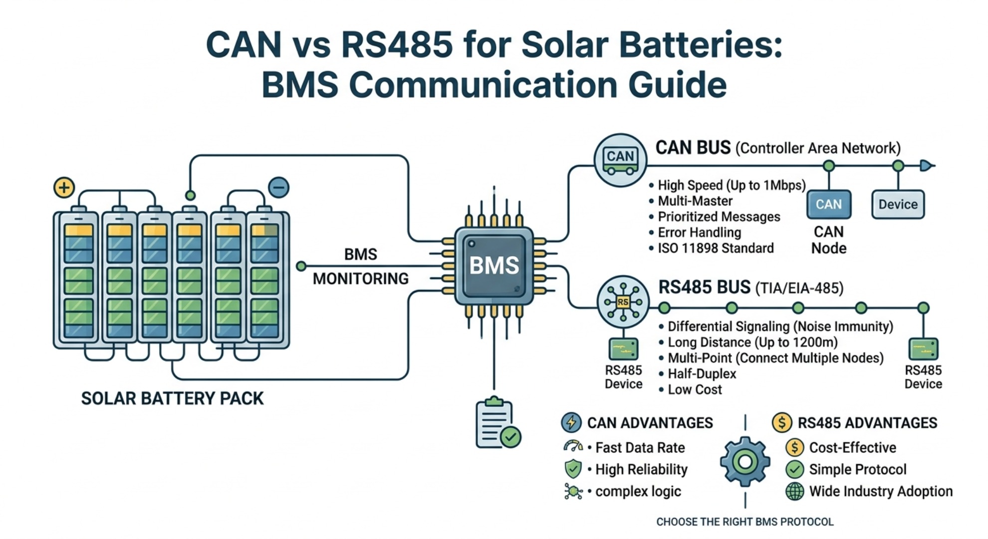
Table of Contents
- Solar Battery Communication Architecture: CAN vs RS485 Topology
- Signal Integrity, Error Handling and EMI Noise Immunity
- BMS Integration Cost and Implementation Complexity
- CAN Bus vs RS485: Side-by-Side Technical Comparison
- Which Protocol to Choose: CAN or RS485 for Solar Storage
- Frequently Asked Questions
In modern energy storage installations, establishing reliable data exchange between the battery management system (BMS) and the solar inverter is critical for safety and operational efficiency. Both Controller Area Network (CAN bus) and Recommended Standard 485 (RS485) serve as dominant physical layers for solar battery communication protocols. While both technologies utilize balanced differential lines to suppress electrical noise, their underlying network topologies, framing protocols, and latency characteristics differ significantly.
Implementing a closed-loop battery communication link enables real-time synchronization of dynamic charging limits, voltage cut-offs, and state-of-charge (SOC) metrics. Without a robust communication pipeline, an energy storage system must rely on conservative open-loop voltage thresholds, which reduces performance optimization and accelerates cell aging. Understanding how CAN bus and RS485 operate under varying electrical loads allows system designers to choose the optimal architecture for their specific battery chemistry and power rating.
Solar Battery Communication Architecture: CAN vs RS485 Topology
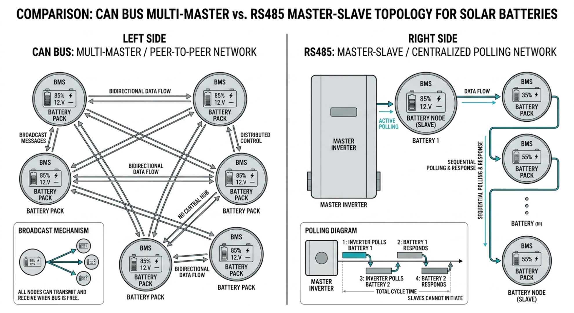
Multi-Master CAN Bus vs Master-Slave RS485

CAN bus utilizes a peer-to-peer, multi-master network topology, allowing any battery pack or management unit on the bus to transmit data whenever the line is free. Bus access conflicts are resolved using Non-Destructive Bitwise Arbitration via Carrier Sense Multiple Access with Collision Resolution (CSMA/CR). This mechanism ensures that high-priority fault alerts—such as over-temperature warnings or over-current spikes—instantaneously preempt routine telemetry data without data loss, as defined in standard CAN bus specifications.
In contrast, RS485 relies on a traditional master-slave architecture where a central primary device (typically the hybrid inverter or system controller) polls secondary nodes sequentially. Secondary battery management units cannot initiate data transmission independently. While this single-master approach prevents packet collisions at the physical layer, it creates a latency bottleneck in large multi-battery clusters, potentially delaying crucial emergency cutoff signals during rapid electrical faults.
Baud Rate, Cable Length and Maximum Distance Limits
The operational performance of both communication buses is subject to a strict trade-off between transmission speed and maximum line length. CAN bus delivers high bandwidth, supporting data transfer rates up to 1 Mbps at short distances under 40 meters. For multi-rack battery installations requiring extended cable runs, reducing the baud rate to 125 kbps allows CAN to cover distances up to 500 meters while maintaining deterministic message delivery.
RS485 excels in wide-area deployments, achieving a maximum cable distance of up to 1,200 meters at lower baud rates (typically 9,600 to 115,200 bps). Although RS485 hardware can theoretically achieve speeds up to 10 Mbps over extremely short runs, energy storage controllers limit baud rates to maintain signal clarity across standard shielded twisted pair cable runs.
Signal Integrity, Error Handling and EMI Noise Immunity
Hardware Message Arbitration and CRC Error Checking
High-reliability energy storage systems demand robust error detection to avoid processing corrupted state data. CAN bus integrates hardware-level error handling directly into its silicon transceivers, using a 15-bit cyclic redundancy check, bit-stuffing validation, and automatic message retransmission. If a node detects a corrupted frame, all nodes reject the message simultaneously, and the sender retransmits automatically without processor intervention.
RS485 functions purely as a physical layer standard under established differential signaling standards. It lacks native frame verification, delegating data packaging and error checking to application-layer protocols such as Modbus RTU. Standard Modbus implementations rely on a software-calculated 16-bit CRC checksum, as documented in the official Modbus RTU specifications. This software dependency adds computational overhead and delays fault recovery during severe packet degradation.
EMI Resistance in Inverter and PCS Noise Environments
Solar energy conversion systems generate significant high-frequency noise through the switching circuits of power conversion systems (PCS) and hybrid inverters. Both CAN and RS485 neutralize inverter electrical noise using balanced differential voltage signals (CAN_H/CAN_L or RS485_A/RS485_B). Electromagnetic interference affecting both conductors equally is rejected by the receiver's differential amplifier.
To prevent wave reflections and signal degradation along the transmission line, both protocols require proper impedance matching across the physical layout. Installing a 120-ohm bus termination resistor at each physical end of the bus absorbs electrical reflections that cause bit errors. While RS485 tolerates wider common-mode voltage swings (-7V to +12V), CAN transceivers provide superior transient voltage protection against sudden inductive surges.
BMS Integration Cost and Implementation Complexity
Integrating RS485 into battery control boards offers significant hardware savings due to the low cost of basic transceiver microchips and ubiquitous UART microcontroller support. This lower system integration cost makes RS485 popular for cost-sensitive residential storage units, auxiliary sensor loops, and entry-level inverter pairings where standard serial transmission is adequate.
CAN bus implementation requires dedicated CAN controllers and specialized physical layer transceivers, slightly increasing BMS transceiver hardware costs. However, CAN offsets this hardware premium by simplifying software complexity. Because collision resolution, message filtering, and error retransmissions are managed automatically by hardware, software developers spend less time building custom error-handling code, reducing long-term firmware development expenses.
CAN Bus vs RS485: Side-by-Side Technical Comparison
| Technical Parameter | CAN Bus Protocol | RS485 Standard |
|---|---|---|
| Network Architecture | Multi-Master (Peer-to-Peer) | Master-Slave (Polled) |
| Max Data Transfer Rate | 1 Mbps (up to 8 Mbps with CAN FD) | Up to 10 Mbps (typically ≤ 115.2 kbps) |
| Max Transmission Distance | ~40m @ 1 Mbps (~500m @ 50 kbps) | Up to 1,200m @ 9.6 kbps |
| Bus Arbitration | Hardware bitwise priority (CSMA/CR) | None (handled by software polling) |
| Error Handling | Hardware CRC, ACK, Bit-stuffing | Application layer (e.g., Modbus CRC) |
| Max Nodes per Bus | 110 to 127 nodes | 32 standard nodes (up to 256 with repeaters) |
| Primary Solar Use Case | Real-time inverter communication, parallel packs | Long-distance telemetry, multi-rack monitoring |
Which Protocol to Choose: CAN or RS485 for Solar Storage
Selecting between CAN bus and RS485 depends on system scale, real-time control requirements, and environmental conditions. For high-voltage battery storage banks, fast-response commercial systems, and multi-pack parallel connections, CAN bus is the clear choice. Its deterministic message delivery and sub-millisecond error signaling guarantee that dynamic current limits are communicated safely during rapid load shifts.
For expansive ground-mounted solar farms, long-distance remote monitoring links, or budget-conscious residential installations where cable runs exceed 50 meters, RS485 remains a practical and dependable solution. By aligning protocol selection with specific distance, speed, and safety parameters, engineers can ensure high uptime and long-term reliability for solar energy storage systems.
Frequently Asked Questions
What is the main difference between CAN bus and RS485 for solar batteries?
The core difference lies in network architecture: CAN bus uses a multi-master peer-to-peer topology with hardware-level priority arbitration, enabling instant fault alerts. RS485 follows a master-slave polled structure where only the central controller can initiate communication. CAN also natively integrates hardware error handling, while RS485 relies on application-layer protocols like Modbus for frame verification.
Is CAN bus better than RS485 for residential solar storage?
It depends on system scale and budget. For small, cost-sensitive residential units with short cable runs, RS485 is a practical, low-cost choice. For multi-pack parallel systems, high-voltage batteries, or installations requiring fast real-time control, CAN bus delivers superior safety and deterministic performance.
How far can CAN bus and RS485 run in solar battery systems?
At 1 Mbps, CAN bus supports up to approximately 40 meters; reducing the baud rate to 50 kbps extends it to around 500 meters. RS485 achieves much longer ranges: up to 1,200 meters at 9.6 kbps, making it ideal for large ground-mounted solar farms and remote monitoring applications.
Which protocol has better noise immunity for solar inverter environments?
Both use balanced differential signaling to reject common electromagnetic interference from inverters and PCS. However, CAN transceivers provide superior transient voltage protection against sudden inductive surges, while RS485 tolerates wider common-mode voltage swings (-7V to +12V).
Is RS485 cheaper than CAN bus for BMS integration?
RS485 has lower upfront hardware costs due to inexpensive transceivers and universal UART microcontroller support. CAN bus requires dedicated controllers and specialized transceivers, increasing hardware costs, but reduces long-term firmware development expenses by offloading error handling and arbitration to hardware.
Can I mix CAN bus and RS485 in one solar battery system?
They cannot be directly connected on the same physical bus, as they use different framing and arbitration rules. You can integrate both standards in a single system using a protocol gateway or converter that translates signals between the two at the system controller level.
How to Buy LiFePO4 Batteries in Bulk
How Many Batteries Can Be Connected in Parallel?