


LFP Expansion Risks: The Voltage Gap Problem
LFP Battery Expansion: The Science Behind Voltage Gaps Explained
On This Page
Expanding an existing Lithium Iron Phosphate (LFP) energy storage array months or years after installation carries significant engineering challenges. While LFP chemistry is widely praised for its thermal stability and long cycle life, adding new battery modules to an aged system introduces operational hazards. The core issue lies in the subtle electrochemistry of LFP cells—specifically, how an extremely flat discharge curve interacts with internal resistance degradation over time.
LFP Voltage Curve: Why State of Charge Estimation Gets Complex
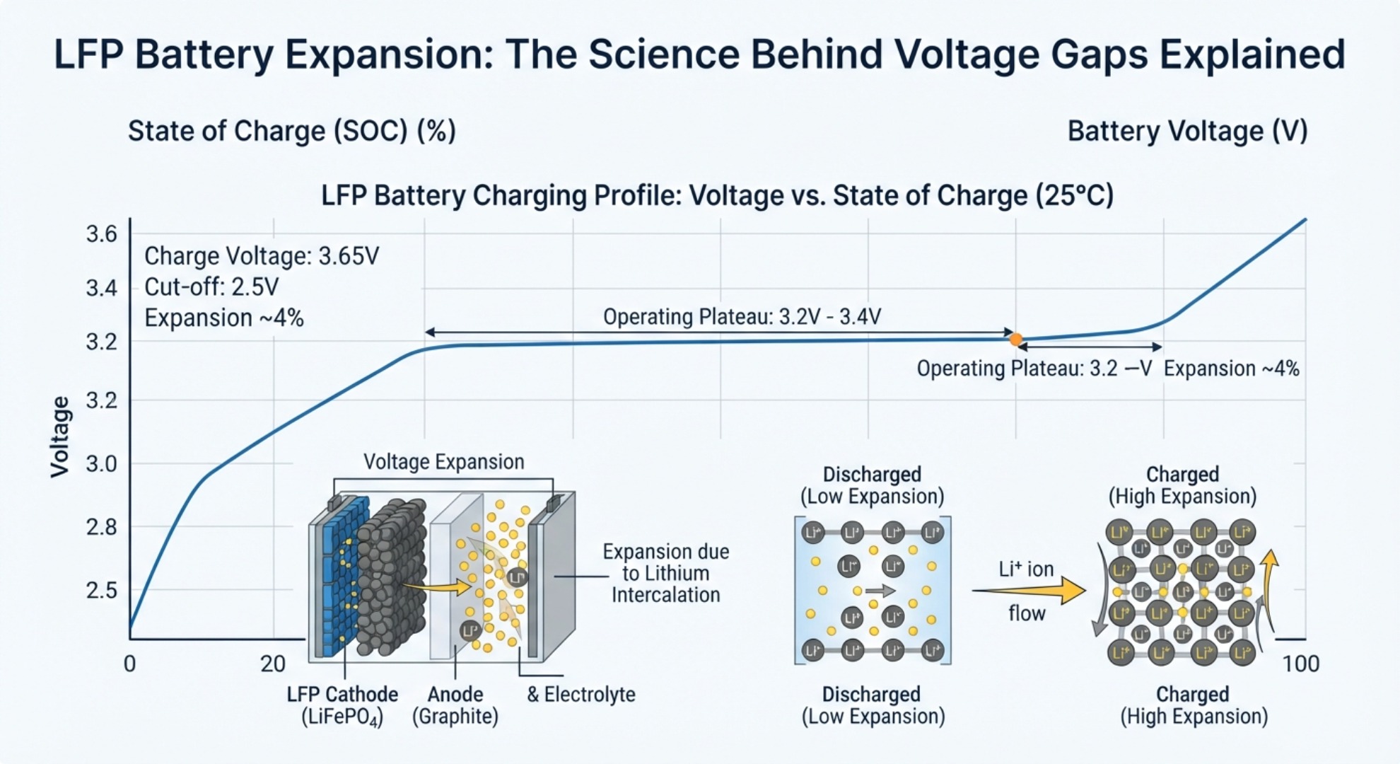
Unlike Nickel Manganese Cobalt (NMC) or lead‑acid chemistries, LFP cells exhibit a distinct phase‑transition behavior during charge and discharge. Research published in the Journal of Power Sources demonstrates that LFP open circuit voltage (OCV) remains nearly constant across 20% to 80% state of charge estimation ranges. A minute voltage difference of just 10 to 20 millivolts can represent a 30% to 40% discrepancy in remaining capacity.
LFP Voltage vs. State of Charge (SoC) Characteristics
3.4V +---------------------------------------------------+ (Near Full)
     |                                          /--------|
3.3V |  ======================================/          |  <- Flat OCV Plateau
     |  (A 10mV drift equals ~30% SoC variance)          |     (20% - 80% SoC)
3.2V |/                                                  |
3.0V +---------------------------------------------------+ (Near Empty)
     0%                      50%                       100%
|
When integrating fresh modules with aged packs, this flat profile makes voltage‑based equalization practically impossible. The system cannot determine true relative capacity based on voltage alone, leading to severe imbalances during load changes.
Internal Resistance Mismatch & Circulating Currents in Aging LFP
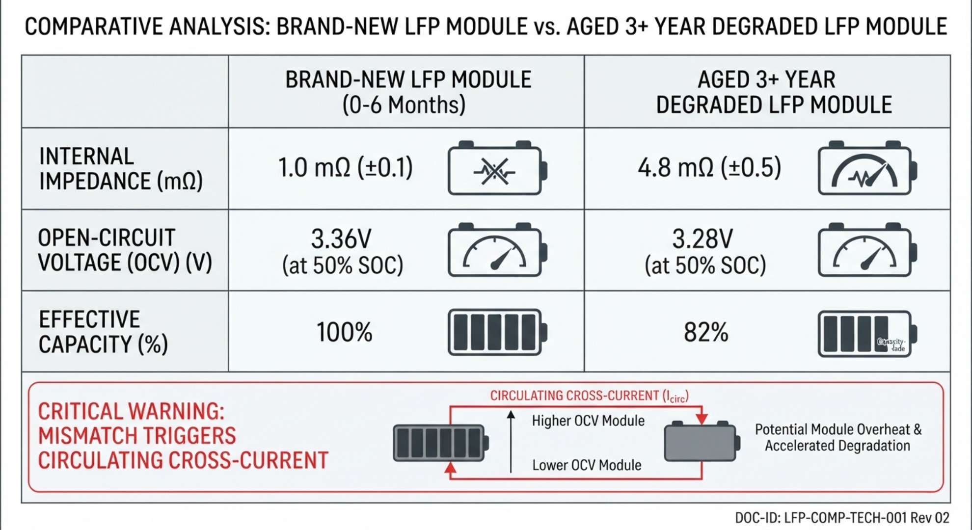
As LFP cells undergo charge‑discharge cycling, solid electrolyte interphase (SEI) layer growth increases their battery internal resistance mismatch. An older module exhibits higher internal impedance and lower actual capacity than a brand‑new counterpart.
| System Metric | New LFP Module | Aged LFP Module (3+ Years) | Impact When Paired |
|---|---|---|---|
| Internal Impedance | Low (~0.5 mΩ) | Higher (~1.2–2.0 mΩ) | Severe current imbalance |
| OCV at 50% SoC | ~3.28 V | ~3.27 V | Triggers massive cross‑currents |
| Effective Capacity | 100% Nominal | ~80–85% Nominal | Premature low‑voltage cutoff |
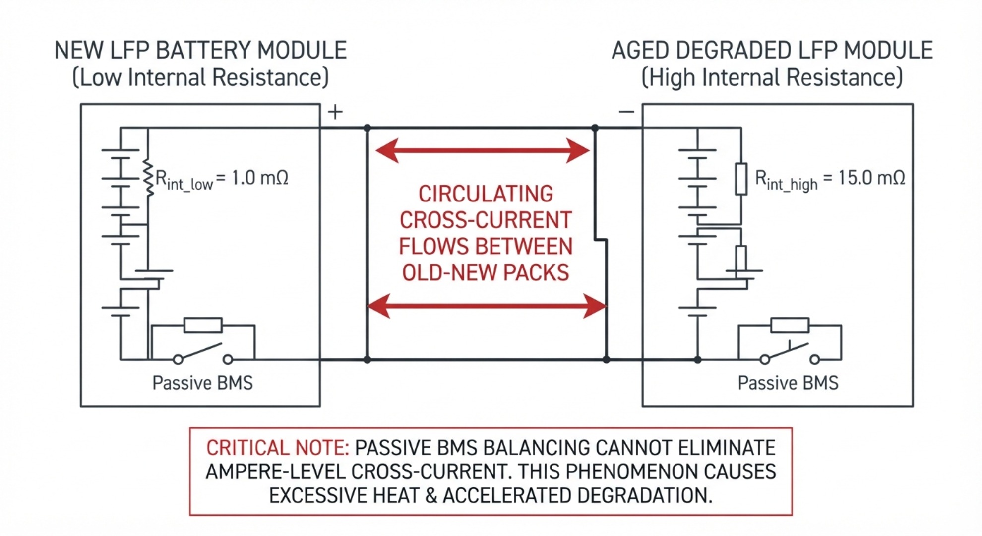
When connected in parallel, the lower impedance of the new pack causes it to absorb a disproportionate share of charge current and deliver higher discharge current. Furthermore, during idle periods, parallel battery cross currents flow from the higher‑potential new pack into the lower‑potential old pack. This continuous circulating current generates localized heat, accelerates capacity fade, and risks tripping overcurrent protection devices.
BMS Limitations in LFP Battery Retrofit: Balancing Explained
Standard energy storage architecture relies on a battery management system balancing protocol to maintain cell uniformity. Passive balancing dissipates excess energy as heat through resistors, typically capped at tiny currents (50 mA to 200 mA).
+-----------------------------------------------------------------+ | LFP Retrofit System Dynamics | | +-----------------------+ +---------------------+ | | | New LFP Module | | Aged LFP Module | | | | Low R_int / High Cap | | High R_int / Low Cap| | | +-----------+-----------+ +----------+----------+ | | +============ Cross ===============+ | | Currents | | Problem: Passive BMS balancing (50-200mA) cannot bridge | | ampere‑level capacity & impedance gaps between generations. | +-----------------------------------------------------------------+ |
These balancing circuits are designed to correct minor manufacturing tolerances within a single production batch, not multi‑ampere disparities between different cell generations. When faced with large capacity and impedance gaps during an energy storage system expansion, standard passive balancing fails to equalize the array. The older module reaches its lower voltage cutoff long before the new module depletes, forcing the BMS to shut down the entire system prematurely and rendering the added capacity unusable.
Mitigating LFP Battery Expansion Risks in Energy Storage
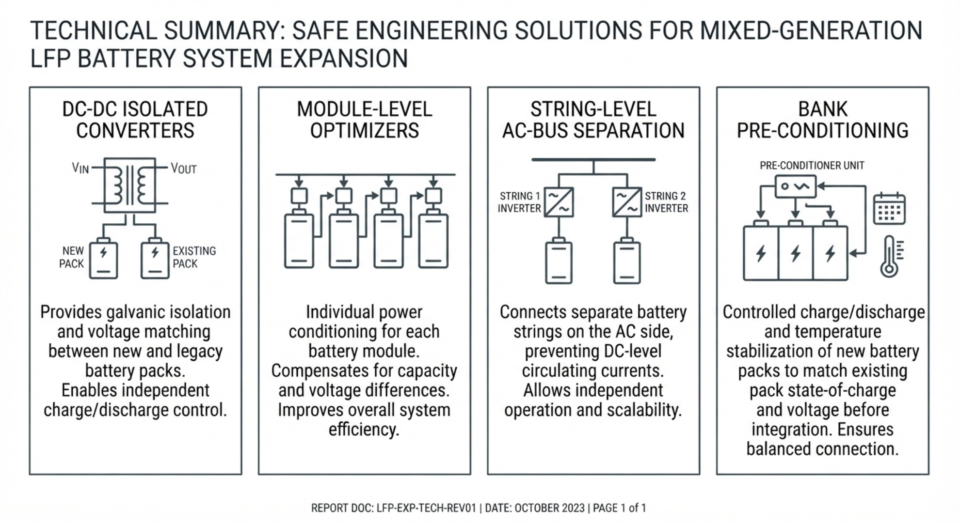
To expand LFP capacity safely without encountering destructive voltage gap issues, operators must implement dedicated engineering controls rather than simple direct‑parallel wiring:
- DC‑DC Isolated Converters: Place dedicated DC‑DC converters between distinct battery strings to actively regulate power flow and isolate voltage differentials.
- Module‑Level Microinverters/Optimizers: Use distributed power electronics to manage each pack independently according to its specific health profile.
- String‑Level Separation: Avoid mixing old and new packs on a shared DC bus; instead, establish completely independent DC sub‑arrays tied together at a central AC bus bar.
- Pre‑Conditioning Integration: Fully charge both old and new banks to their upper cutoff plateau before commissioning to align initial voltage states as closely as possible.
Understanding the electrochemistry behind lithium iron phosphate degradation allows engineers to design resilient architectures that bypass the physical risks of mixing battery generations.

JM New Energy Technology



How to Calculate the Right kWh Capacity
LFP Battery Sizing vs Later Parallel Expansion