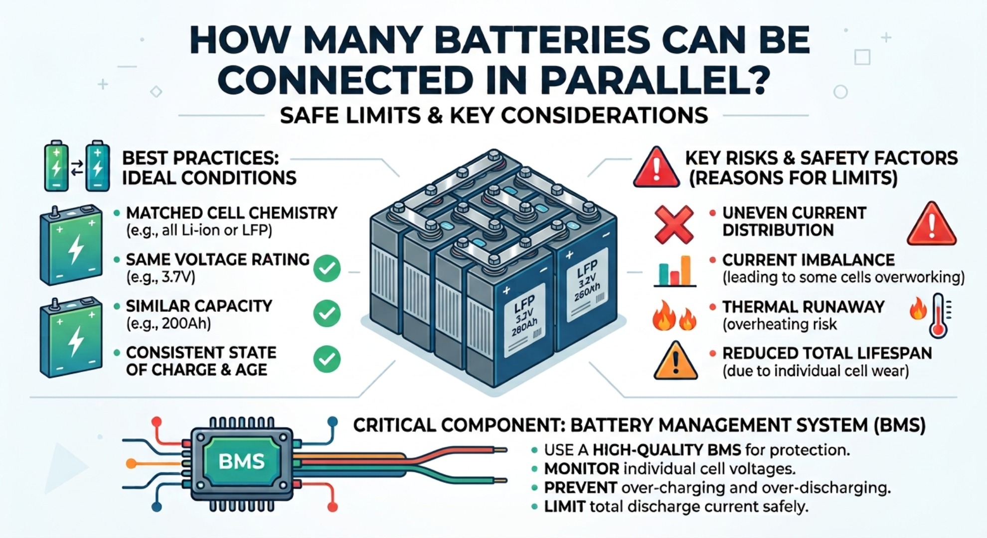



Passive vs Active BMS Balancing for LFP Batteries
Passive vs Active BMS Balancing for LFP Batteries
A Technical Guide to Cell Balancing Strategies for Lithium Iron Phosphate Energy Storage Systems
Consistent cell voltage is the foundation of reliable LFP battery pack performance. The choice between passive and active BMS balancing directly shapes real‑world system efficiency, thermal stability, usable capacity retention and overall service life across residential off‑grid setups, commercial backup power and grid‑tied industrial energy storage. Unlike NCM batteries with clear voltage gradients, LFP’s flat voltage plateau makes cell balancing far more critical in daily operation. Minor cell inconsistencies left unaddressed will compound over cycles, triggering measurable capacity loss and premature pack failure in the long run.
LFP Cell Imbalance & Voltage Plateau Explained
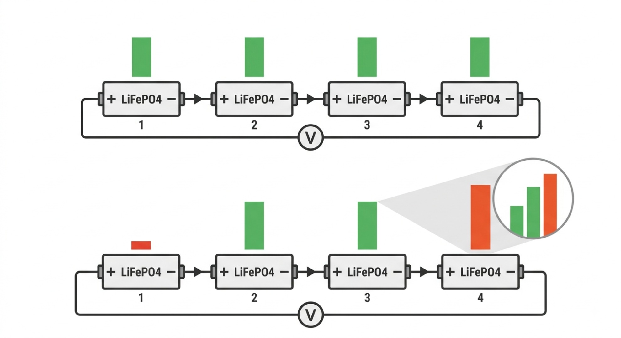
Series‑connected LFP battery packs rely on matched cell performance to deliver full rated capacity. In field operation, perfect cell consistency is impossible to sustain permanently. Cell imbalance describes the gradual divergence of state of charge, internal resistance and open‑circuit voltage across individual cells in a series string. This issue stems from minor manufacturing tolerances and uneven operating conditions. Without proper BMS balancing, the weakest cell dictates the entire pack’s operating limits. It hits full charge first to cut off charging and depletes faster during discharge, leaving the rest of the pack underutilized and significantly reducing total usable energy output.
LiFePO4 Flat Voltage Curve Impact
LFP chemistry stands out from ternary lithium batteries due to its extremely flat charge and discharge voltage plateau. Under normal operating conditions between 20% and 80% SOC, cell voltage stays steady at 3.20V to 3.25V. Voltage barely shifts even with large changes in stored energy.
This creates a critical monitoring blind spot for conventional voltage‑based BMS. Small SOC gaps between cells cannot be detected through regular voltage sampling during routine cycling. Imbalance builds up silently over dozens of cycles and only becomes visible when cells approach overcharge above 3.45V or deep discharge below 3.0V. By the time voltage differences show up, capacity drift has already settled in, making slow passive balancing ineffective for quick correction. This unique trait makes continuous, precise balancing a must for long‑term LFP pack reliability.
Causes of Capacity Drift in LFP Packs
LFP capacity drift develops gradually from both manufacturing imperfections and operational wear. During production, tiny variations in electrode coating thickness, electrolyte filling volume, separator porosity and initial internal resistance create small performance gaps between cells. These gaps grow wider with every charge and discharge cycle.
Field operating conditions worsen cell inconsistency. Uneven heat distribution across the pack — caused by poor ventilation, irregular mounting or heat buildup near high‑current terminals — leads to different self‑discharge rates. Warmer cells lose charge faster and gradually fall behind cooler cells in the string. High‑rate charging, frequent partial cycling, long‑duration floating charge and gradual electrolyte aging further amplify cell discrepancies. After 100 to 500 cycles, these small deviations accumulate into obvious capacity inconsistency, lowering overall system efficiency and accelerating localized cell aging.
Passive BMS Balancing for LiFePO4 Storage
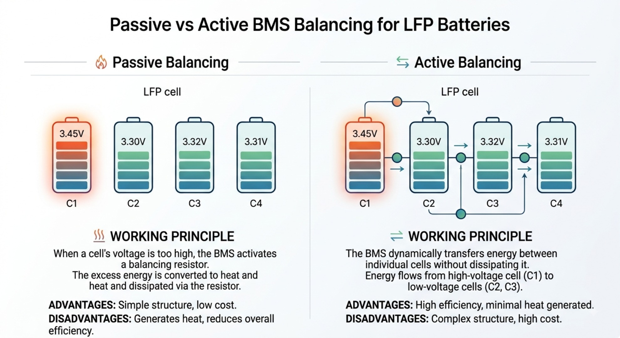
Passive balancing, also known as resistive bleed balancing, is a mature, cost‑efficient solution widely used in consumer and small‑scale LFP BMS units. It only works during the constant voltage charging stage. The core goal is to bleed down overcharged cells to align the SOC of the entire battery string.
Resistor Energy Dissipation Mechanism
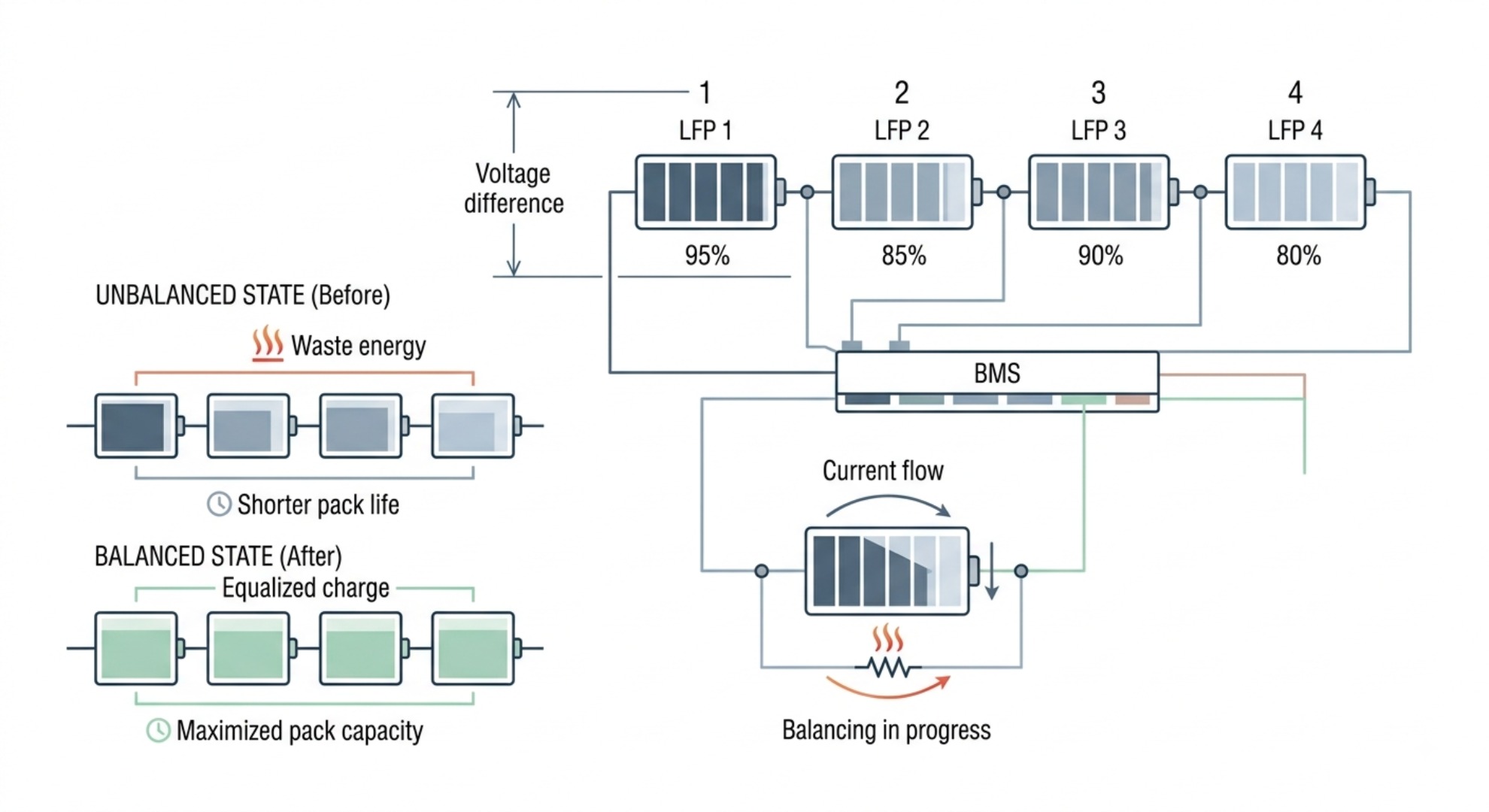
A typical passive balancing system consists of voltage sampling circuits, a main MCU, MOSFET switches and power balancing resistors. When the pack enters the CV charging phase, the BMS monitors individual cell voltages in real time. Once a cell exceeds the LFP balancing threshold of 3.40V to 3.45V, the corresponding MOSFET turns on.
This connects the overvoltage cell in parallel with a power resistor. Excess electrical energy converts to heat via Joule heating and dissipates into the ambient air. The bleeding process continues until the cell voltage drops to match the rest of the string. After all cells reach uniform top‑end voltage, the pack finishes full charging. This simple mechanism prevents single‑cell overcharge and maintains basic cell consistency for daily operation.
Limitations & Thermal Management Challenges
Despite low cost and simple circuitry, passive balancing has clear drawbacks that limit its use in high‑capacity, high‑cycle LFP systems. First, it only works during CV charging. It provides no correction during discharge, standby or dynamic high‑load operation. Any imbalance generated outside the charging phase remains unaddressed and accumulates over time.
Second, balancing current is heavily capped. To avoid overheating and BMS hardware damage, passive balancing current is restricted to 30mA to 200mA. For mainstream 280Ah to 314Ah large prismatic LFP cells, a standard 100mA balancing current requires dozens of full cycles to fix even minor 1–2% SOC deviations. In frequently cycled storage systems, imbalance builds faster than passive balancing can correct, resulting in steady capacity attenuation.
Third, this method creates noticeable energy waste and thermal risks. All excess energy is converted to waste heat, cutting annual system energy efficiency by 2–5%. In compact battery enclosures with limited heat dissipation, continuous balancing heat raises local temperatures, speeds up cell aging and can even trigger BMS over‑temperature protection, which disables balancing entirely until temperatures recover.
Active BMS Balancing: Efficient Energy Redistribution
Active balancing was developed to solve the core flaws of passive resistive balancing. Instead of wasting excess cell energy as heat, active BMS uses high‑efficiency power electronics to transfer surplus charge from higher‑SOC cells to lower‑SOC cells. It reuses energy rather than dissipating it and delivers real‑time cell equalization across all operating states.
Inductive & Capacitive Energy Transfer
Commercial active balancing hardware mainly adopts two reliable technical routes: capacitive charge transfer and inductive energy transfer, both delivering high conversion efficiency. Capacitive active balancing uses high‑frequency switching capacitors as temporary energy storage carriers. The BMS controls high‑speed switch arrays to capture surplus energy from high‑voltage cells and deliver it to undercharged cells in the same string.
Inductive active balancing uses inductors or miniature high‑frequency transformers for energy buffering and transfer, offering better power tolerance and operational stability than capacitive designs. Both approaches avoid energy waste, with conversion efficiency ranging from 85% to 92%. Unlike passive balancing that only reacts at top‑end charging voltage, active circuits detect tiny SOC differences on LFP’s flat voltage plateau. This enables precise equalization even in the normal 20%–80% SOC operating window where most system cycling occurs.
Balancing Speed & Current Capabilities
The biggest practical advantage of active balancing is fast correction speed and full‑state dynamic operation. Standard active BMS provides continuous balancing current from 1A to 5A, while industrial high‑power versions reach 10A or higher — dozens of times faster than passive solutions. Imbalance issues on large‑capacity LFP packs that take months to resolve with passive balancing can be fixed within 1 to 3 full charge cycles with active systems.
More importantly, active balancing works consistently during charging, discharging, standby and floating charge. It offsets cell drift caused by high‑rate cycling, uneven thermal distribution and long idle periods, stopping cumulative capacity deviation before it becomes permanent. This round‑the‑clock balancing capability is why active BMS preserves full rated capacity on large LFP energy storage packs over long service periods.
Passive vs Active BMS: Technical Comparison
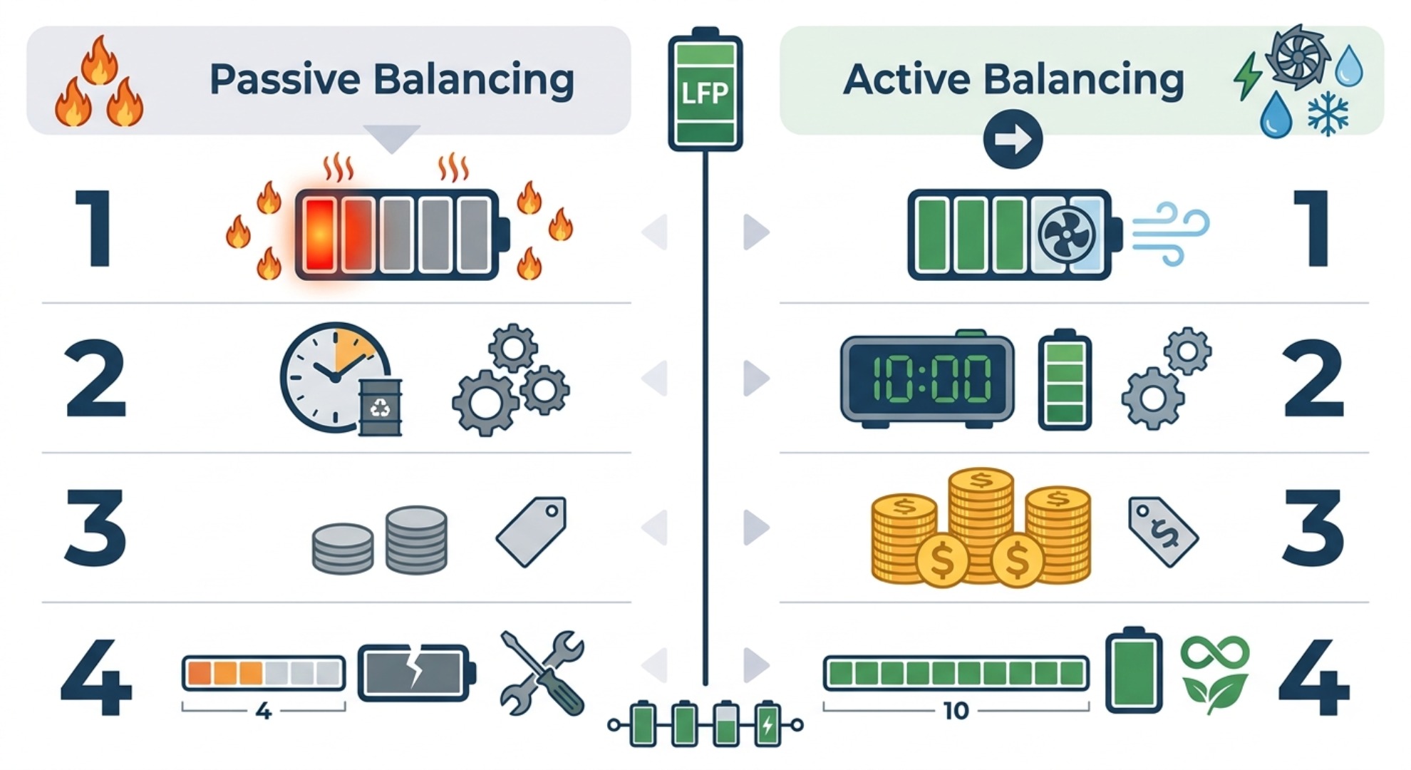
Full Technical Comparison Table
| Technical Dimension | Passive BMS Balancing | Active BMS Balancing |
|---|---|---|
| Working Principle | Resistive energy dissipation; bleeds excess cell voltage into heat | Inductive/capacitive energy transfer; reuses charge across mismatched cells |
| Balancing Current | 30mA – 200mA (very low) | 1A – 10A (high‑speed industrial grade) |
| Operating Scenarios | Only active during CV charging (static, charge‑only) | Covers charge, discharge, idle and standby (full dynamic balancing) |
| Energy Efficiency | Low; 2–5% annual energy loss from heat dissipation | High; 85–92% conversion efficiency with minimal energy waste |
| Flat Plateau Adaptability | Poor; only corrects extreme voltage deviations at charge limits | Excellent; identifies and fixes minor SOC drift in normal voltage plateau range |
| Balancing Speed | Slow; requires dozens of cycles to correct small imbalance | Fast; resolves typical cell mismatch within 1–3 cycles |
| Thermal Risk | Moderate to high; continuous heat buildup during balancing | Low; negligible heat generation with energy transfer design |
| Circuit Complexity | Simple analog/digital circuit; low failure rate | Complex power electronics; requires precise high‑frequency control |
| Hardware Cost | Low; ideal for cost‑sensitive low‑power systems | Higher upfront cost; premium for industrial and high‑capacity deployments |
| Long‑Term Capacity Retention | Average; gradual capacity fade over repeated cycling | Superior; sustains full pack capacity and minimizes aging drift |
Choosing the Right BMS for Your LFP Application
The selection between passive and active balancing depends on battery capacity, cycle frequency, operating environment, system power rating and long‑term operational returns. No single solution fits all scenarios. Proper matching balances upfront cost, daily energy efficiency and total pack service life.
When Passive Balancing Is Enough
Passive resistive balancing remains the most cost‑effective and reliable option for low‑intensity LFP applications. It works perfectly for small and medium battery packs under 100Ah with low cycle counts and long static standby periods. Common use cases include household backup power units, low‑power emergency supplies, intermittent‑use light electric vehicles and low‑cycle solar backup systems that stay fully charged most of the time.
In these scenarios, cell imbalance accumulates very slowly. The low‑current bleeding function corrects minor voltage gaps gradually during routine full charging cycles. Its simple circuit structure delivers ultra‑low failure rates and zero ongoing maintenance costs, making it the best cost‑performance choice for light‑duty applications. For users prioritizing basic stability and low initial investment, passive balancing fully meets daily operational demands.
When Active Balancing Is Essential
Active balancing is a necessary upgrade for all high‑capacity, high‑cycle and high‑value LFP energy storage systems. For 200Ah+ prismatic LFP packs including mainstream 280Ah and 314Ah models, frequent charge‑discharge cycling creates continuous cell drift. Passive balancing cannot keep up with the speed of imbalance accumulation, leading to 10–20% irreversible capacity loss within one to two years of operation.
Mandatory application scenarios include large‑scale solar BESS stations, commercial peak‑shaving and load‑shifting storage, industrial UPS systems, high‑power off‑grid storage arrays and other high‑frequency cycling power systems. Active dynamic balancing corrects cell mismatch in real time, maintains consistent cell parameters long‑term, reduces single‑cell thermal stress and extends overall pack lifespan by 20–30%. For industrial energy storage assets, the extra cost of active BMS is quickly offset by reduced cell replacement frequency and improved energy throughput, delivering better long‑term project ROI.
LiFePO4 BMS Reset & Troubleshooting Guide
LiFePO4 Battery Heater vs. Insulation