


LiFePO4 BMS Reset & Troubleshooting Guide
LiFePO4 BMS Reset & Troubleshooting: Complete Step‑by‑Step Guide

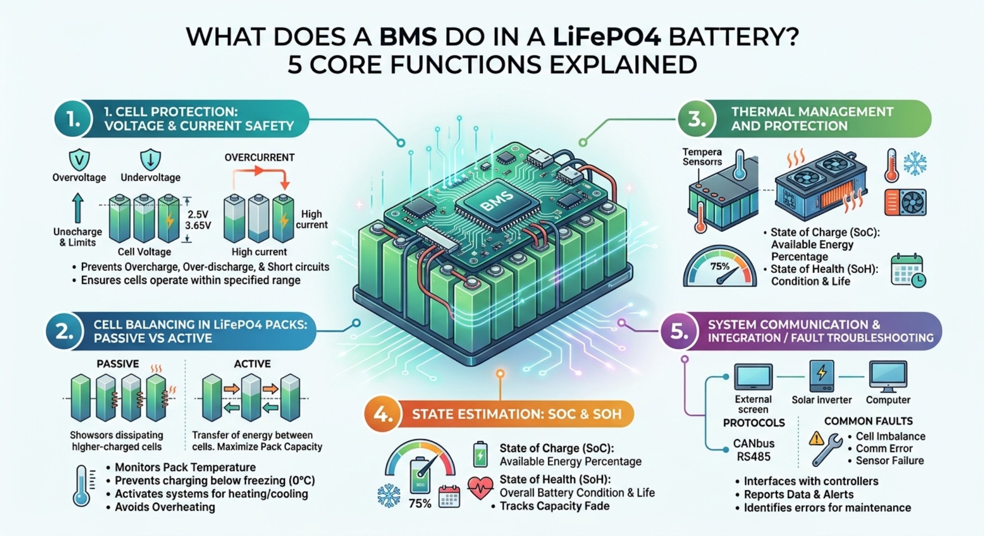
Every LiFePO4 battery pack relies on a BMS for core safety protection. Unlike traditional lead‑acid batteries, lithium iron phosphate cells have strict voltage, current and temperature operating limits. Once operating parameters go out of range, the BMS will immediately cut off charge and discharge circuits. This is a normal safety protection mechanism, not battery failure, which effectively prevents cell aging, capacity loss, bulging and thermal risks. Read our LiFePO4 battery degradation guide to learn more about cell aging.
Most users misjudge a 0V terminal reading as a dead battery. In actual maintenance scenarios, the internal cells still retain voltage. The BMS simply locks the output MOSFETs to protect the cells. Standard reset and troubleshooting methods can recover almost all locked LiFePO4 packs without replacement. This guide summarizes field‑tested reset steps, common fault causes, practical solutions and daily maintenance rules, applicable to 12V, 24V, 48V and high‑voltage series LiFePO4 battery systems.
Understanding LiFePO4 BMS Protection Mode & Sleep State

Common Causes of BMS Sleep State & Protection Triggers
Over‑discharge protection is the most common fault. The standard low cutoff voltage for a single LiFePO4 cell is 2.5V. Long‑term standby and light load operation will produce parasitic current, including inverter standby power and monitoring module power consumption, which slowly drains cell voltage. When any single cell drops below 2.5V, the BMS will fully lock the discharge output. Long‑term deep over‑discharge will cause irreversible capacity attenuation, making reset invalid in severe cases.
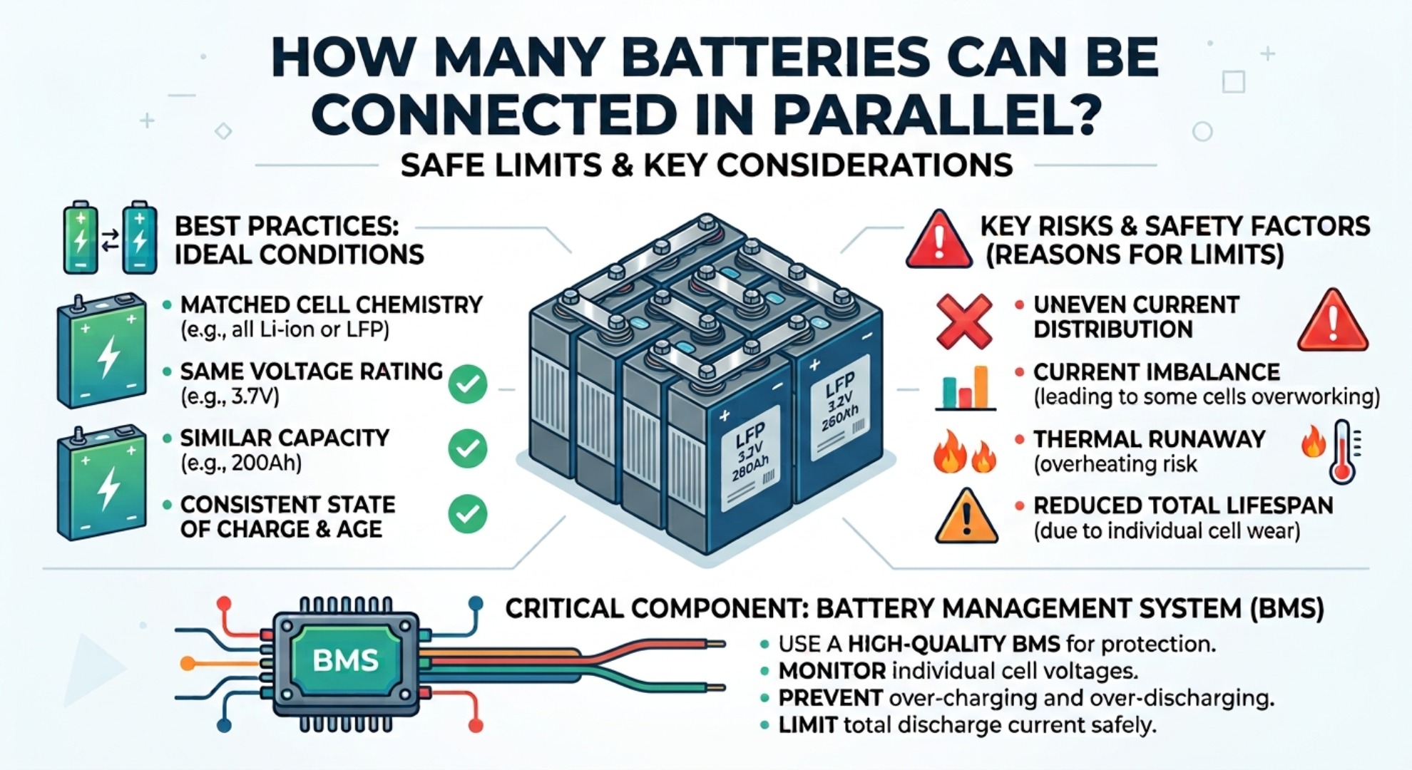
Cell voltage imbalance is another frequent trigger. Multi‑series battery packs (4S, 8S, 16S, etc.) have subtle differences in internal resistance and capacity between individual cells after long‑term use. After repeated charge and discharge cycles, voltage gaps gradually form. During charging, the cell with the highest voltage reaches the 3.65V upper limit first and triggers high‑voltage cutoff. During discharging, the lowest voltage cell triggers low‑voltage cutoff first. Even if the total pack voltage is normal, the whole system will stop working. Severe imbalance leads to frequent BMS tripping and reduced available capacity. Learn more in our article about passive vs active BMS balancing for LFP batteries.
Overcurrent and short‑circuit protection usually occurs at equipment startup. Inverters and motor loads are equipped with large capacitors, which generate instantaneous inrush current far exceeding the BMS continuous current rating. This instant high current will trigger short‑circuit protection even with normal load power. Temperature protection is also easy to ignore: charging below 0°C or operating above 60°C will disable charge and discharge functions to protect cell chemical stability. Check our notes on LiFePO4 battery cold weather charging for practical low‑temperature operation tips.
How to Reset a LiFePO4 Battery BMS: 4 Proven Methods

BMS reset only works after eliminating hidden faults such as short circuits and overheating. Follow the steps from simple to professional. Most locked batteries can be recovered through the first two conventional methods.
Step 1: Disconnect All External Loads and Chargers (Mandatory Pre‑operation)
Completely disconnect all loads connected to the battery terminals, including inverters, solar charge controllers, DC electrical equipment and parallel battery groups. For solar power systems, disconnect PV panel lines at the same time to cut off all input and output current.
Leave the battery standing for 30 to 60 seconds after disconnection. Most transient overcurrent and short‑circuit latch faults will be automatically cleared. This step avoids secondary protection triggers during reset and is the basic premise of all BMS recovery operations.
Step 2: Connect a Compatible Lithium Battery Charger (Most Common Fix)
Ordinary lead‑acid chargers cannot wake locked LiFePO4 batteries. Users must use a dedicated LiFePO4 charger with 0V wake‑up function. When the BMS is locked, the terminal outputs no voltage, and ordinary chargers will judge the battery as open circuit and refuse to work.
The dedicated lithium charger outputs tiny detection current to activate the BMS auxiliary power supply. After the BMS chip wakes up and detects normal charging parameters, it will close the MOSFET switch and start normal charging. This method solves more than 80% of low‑voltage lockout faults caused by daily over‑discharge.
Practical tip: If the charger has no response within 2 to 3 minutes, re‑plug the terminals to avoid long‑term idle detection failure.
Step 3: Apply a Parallel Jump‑Start Voltage Pulse (For Stubborn Deep Discharge Locks)
For deeply discharged batteries that cannot be woken by a charger alone, use the parallel jump‑start method. Prepare a fully charged 12V lead‑acid battery or adjustable DC power supply, connect positive to positive and negative to negative with the locked LiFePO4 pack, and keep the parallel connection for only 3 to 5 seconds.
The short voltage pulse supplies working power to the BMS control circuit to release deep sleep lockout. Do not keep long‑term parallel connection to prevent instantaneous current impact from damaging the BMS sampling circuit. After successful wake‑up, disconnect the auxiliary power immediately and use a dedicated lithium charger for low‑current charging and cell balancing.
Step 4: Execute a Digital BMS Soft Reset (For Smart BMS)
Smart BMS with Bluetooth, RS485 or CAN communication supports software soft reset. Connect the battery through the official matching mobile app or computer diagnostic software to view specific fault records, including over‑discharge, overcurrent, over‑temperature and other trigger causes.
Manually clear historical fault codes in the software, restart the BMS system and restore default protection parameters. This method is suitable for frequent false tripping and unknown lock faults. It can accurately locate hidden circuit and parameter anomalies that manual reset cannot solve, and is the preferred maintenance method for high‑end smart battery packs.
LiFePO4 BMS Troubleshooting Matrix: Faults & Fixes

Low Voltage Cutoff & Cell Voltage Imbalance Solutions
Do not replace BMS or cells blindly when the battery fails to charge or discharge. Use a multimeter to test two sets of key data first: total voltage of battery main terminals and single‑cell voltage of balance wires. If the terminal voltage is 0V while single cells still have 2.0V to 3.0V voltage, it is purely BMS protection lock. If single‑cell voltage is continuously lower than 2.0V, partial cell failure may exist.
| Fault Symptom | Observed Voltage / Behavior | Underlying Root Cause | Corrective Action |
|---|---|---|---|
| Low Voltage Cutoff (LVC) | 0V terminal reading, charger fails to start, no power output | Single cell deep discharge below 2.5V, long‑term standby parasitic drain | Disconnect all loads first; use 0V wake‑up lithium charger or 3‑5s 12V parallel jump pulse; perform low‑current charging after wake‑up |
| High Voltage Cutoff (HVC) | Charging stops early, unable to reach full capacity, intermittent charging interruption | Cell voltage imbalance causes individual cells to exceed 3.65V upper limit | Stop high‑current charging; enable BMS balancing function; use low‑current slow charging to balance cell voltage consistency |
| Overcurrent / Short Circuit | Power cuts off immediately after load startup, frequent BMS tripping | Load startup inrush current exceeds BMS peak discharge specification | Disconnect loads and wait 30s for automatic reset; replace undersized BMS; install pre‑charge resistor for capacitive loads |
| Temperature Lockout | No charge/discharge in extreme temperature environments, works normally at room temperature | Ambient temperature below 0°C or above 60°C, loose temperature sensor wiring | Move battery to 10‑45°C constant temperature environment; check and fasten temperature sensor probe; prohibit low‑temperature charging |
Overcurrent, Short Circuit & Thermal Protection Fixes
Frequent overcurrent tripping is not always caused by load overload. Most inverters have built‑in large‑capacity capacitors, which generate huge instantaneous current at startup, far exceeding the BMS continuous current rating. Simply increasing BMS current cannot solve the problem. Installing a pre‑charge resistor to buffer startup inrush current is the fundamental solution.
Most cell imbalance faults are caused by abnormal balance wiring. Inspect the battery balance wires for loose pins, oxidized contacts, broken lines and water corrosion. Abnormal sampling signals will cause BMS misjudgment of cell voltage, resulting in random power cutoff and charging failure. When the voltage difference between cells exceeds 0.1V, manual low‑current balancing is required to restore consistency, otherwise the battery usable capacity will decline year by year.
Temperature protection faults include environmental over‑temperature and sensor failure. Batteries placed in closed cabins, high‑temperature outdoor environments or sealed electrical boxes for a long time will accumulate heat and trigger lockout. Loose or aging thermistors will also cause false over‑temperature alarms. Regular inspection of sensor installation and battery heat dissipation conditions can avoid most thermal faults. For thermal management solutions, review our comparison of LiFePO4 battery heater vs insulation.
BMS Protection Lockout Prevention
Most BMS protection faults can be avoided through standardized use and daily maintenance. First, ensure system parameter matching. Solar controllers, inverters and battery monitors must be set according to LiFePO4 parameters, not lead‑acid battery parameters. Mismatched charging and cutoff voltages are the main cause of early charging termination and over‑discharge lockout.
Standardize charging and storage habits. Do not store fully discharged batteries for more than 7 days. For long‑term idle batteries, charge to 50%‑70% SOC and disconnect all external loads to eliminate parasitic power consumption. Never charge LiFePO4 batteries in environments below 0°C, as low‑temperature charging will cause irreversible cell damage and frequent protection tripping.
Optimize wiring and heat dissipation. Fasten high‑current terminals firmly to avoid virtual connection and heat generation. Place batteries in dry, ventilated and constant‑temperature environments, avoiding direct sunlight, rain and closed heat accumulation. Regularly check balance wires and temperature sensors to ensure stable signal transmission.
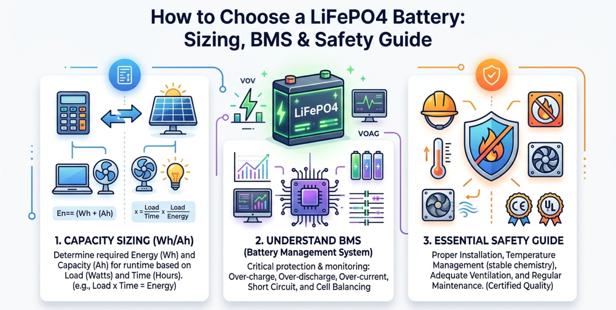
Reasonably match BMS current specifications. The BMS continuous discharge current should be 1.2 to 1.5 times the maximum load working current to reserve margin for instantaneous inrush current. Avoid long‑term full‑load operation of the battery system, which effectively reduces BMS fatigue tripping and extends the overall service life of LiFePO4 packs.
LFP Battery Winter Performance: Cold Weather Case Study
Passive vs Active BMS Balancing for LFP Batteries